
Uneven wear across the width of a roller chain — where one side of the inner link plates shows more wear than the other, or where the rollers show asymmetric wear on one face — is not a random quality variation. It is a mechanical signature that points directly to a specific cause in the drive system. Once you understand the three main causes of asymmetric chain wear, diagnosing the problem from the wear pattern alone becomes straightforward. More importantly, identifying the cause before installing a replacement chain is the only way to prevent the same wear pattern from recurring on the new chain within the same time frame.
What Asymmetric Wear Actually Looks Like
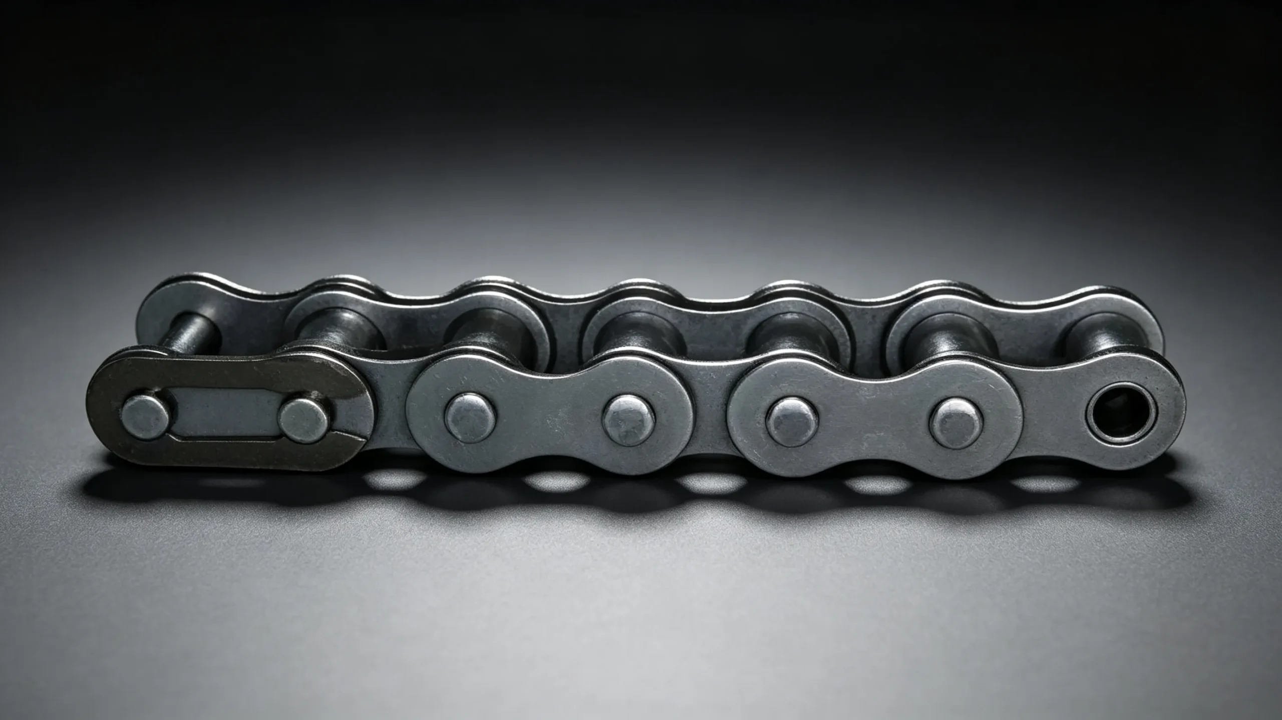
Uneven side wear in roller chain is most visible on the inner faces of the inner link plates — the surfaces that face toward the sprocket during operation. In a correctly aligned drive, these faces should show minimal wear because they do not contact the sprocket tooth sides during normal engagement. When these faces show polishing, scoring, or material removal on one side only, lateral forces are pushing the chain against the sprocket tooth face consistently from one direction.
The rollers can also show asymmetric wear — one end of the roller outer surface more worn than the other, or the roller bore showing heavier wear on one side. In severe cases, the inner plates of one side of the chain show visible scoring while the other side shows clean, unworn surfaces. This lateral asymmetry is physically impossible if the chain is running in the plane of the drive — it can only occur if a lateral force is displacing the chain toward one side of the sprocket.
Cause 1: Sprocket Misalignment — The Most Common Cause
Lateral misalignment between the driving and driven sprockets is by far the most common cause of asymmetric roller chain wear. When the face planes of the two sprockets are not coplanar — either angled relative to each other (angular misalignment) or offset parallel to each other (offset misalignment) — the chain must run at an angle through the engagement arc to bridge the gap between them. This angular running forces the inner plate faces into contact with the tooth sides of one sprocket on every engagement cycle, generating the one-sided lateral wear pattern.
The magnitude of wear increases with the degree of misalignment. For angular misalignment, even 0.5 degrees of angular error between sprocket face planes generates measurable lateral plate face wear at moderate speeds and loads. For offset misalignment, displacement of more than 1 mm from coplanar alignment in a standard-width chain produces visible inner plate face contact marks within a few hundred operating hours.
Diagnosing Misalignment
The diagnostic test for sprocket misalignment is a straight-edge check across the face planes of both sprockets. Place a metal straight edge or laser alignment tool against the face of the larger sprocket and extend it toward the smaller sprocket. In a correctly aligned drive, the straight edge should contact both sprocket faces simultaneously at two points. Any gap between the straight edge and either sprocket face indicates misalignment. Measure the gap at the far sprocket to quantify the offset.
Cause 2: Shaft Deflection Under Load
In drives where the shaft carrying the driven sprocket is long and lightly supported — such as a conveyor tail shaft with a single bearing on each side of a wide belt — the shaft deflects under the combined weight of the chain tension and the shaft mass. This deflection tilts the sprocket relative to the driving sprocket, generating an angular misalignment that increases proportionally with the applied chain tension and shaft span.
The diagnostic signature of deflection-induced lateral wear is that the wear pattern changes with load: the chain shows minimal asymmetric wear at low load and increasing one-sided wear as load increases. This load-dependent pattern distinguishes deflection from geometric misalignment (which produces a constant wear pattern regardless of load). Correcting shaft deflection requires either adding a third bearing mid-span, shortening the shaft span, or increasing the shaft diameter to raise its bending stiffness.
Cause 3: Chain Running Against a Guide or Guard
When a chain runs in close proximity to a guide rail, housing wall, or safety guard, any lateral movement in the chain — from chordal action, shock loading, or minor tension variation — can cause the chain to contact the guide intermittently. If the guide contacts one side of the chain consistently, the result is one-sided plate face wear that is easily mistaken for misalignment-induced wear. The diagnostic distinction is the location of the wear: guide-contact wear appears on the outer face of the outer plates (the exposed side of the chain), while misalignment wear appears on the inner face of the inner plates (the side facing the sprocket).
Check the clearance between the roller chain and any adjacent guide, housing, or guard in the drive system. A minimum clearance of 5 to 10 mm between the chain outer plates and any fixed surface is recommended for most drives. Where tight packaging makes this clearance impossible to achieve, use a guide rail material (nylon, polyethylene) that is significantly softer than the chain plates — the guide wears rather than the chain.
Cause 4: Bent Sprocket or Sprocket Running Off-Centre
A sprocket that has been damaged by impact — struck by a foreign object, dropped during installation, or deformed by a previous chain failure — can run with an eccentricity or lateral wobble that generates periodic lateral loading on the chain. This produces an asymmetric wear pattern that is rhythmic at the sprocket rotation frequency — the wear is heavier on links that engage during the portion of the sprocket revolution when the wobble pushes the chain laterally, and lighter on links that engage during the opposite portion.
Diagnosing a bent or off-centre sprocket requires observing the sprocket during operation (with appropriate safety precautions) and checking for visible lateral movement of the sprocket face. A dial indicator held against the sprocket face while rotating the shaft by hand will quantify the runout. Lateral runout exceeding 0.5 mm (or 1 mm in larger sprockets) is cause for sprocket replacement before installing new chain.
Correcting Asymmetric Wear: A Systematic Approach
| Wear Location | Indicates | Diagnostic Test | Correction |
|---|---|---|---|
| Inner face of inner link plates | Sprocket misalignment or shaft deflection | Straight-edge across both sprocket faces; measure shaft deflection under load | Re-align sprockets; add bearing support if deflection-driven |
| Outer face of outer link plates | Chain contacting a guide or guard | Check clearance to all adjacent surfaces | Increase clearance; use soft guide material |
| One end of roller surface | Angular sprocket misalignment | Straight-edge check; check sprocket parallelism | Re-align to coplanar face planes |
| Asymmetric elongation across width | Bent shaft or eccentric sprocket | Dial indicator check of sprocket lateral runout | Replace damaged sprocket; straighten or replace shaft |
| Uniform wear both sides | Correct alignment — normal service wear | No diagnostic action required | Continue normal maintenance programme |
Why Correcting the Cause Matters Before Chain Replacement
Replacing a roller chain that shows asymmetric wear without correcting the underlying cause is the most reliable way to produce the same wear pattern on the replacement chain in the same time frame. The geometric condition that generated the lateral forces on the old chain — misalignment, shaft deflection, guide clearance — still exists in the drive after the chain is replaced. The new chain inherits the same condition and begins to show the same wear within hours of installation.
The correct sequence is: examine the old chain for wear pattern; identify the cause; correct the drive system condition; then install the new chain. For misalignment correction, re-align the sprockets and verify with the straight-edge check before the new chain goes on. For shaft deflection, add the necessary bearing support. For guide clearance, adjust the guide position or replace with a softer material. Only after the cause is corrected should the new chain be installed — then it will achieve its full rated service life rather than repeating the predecessor failure.
EverPower Roller Chains Australia provides technical support for roller chain wear diagnosis and specification. If your chain is showing asymmetric or premature wear, contact our Sydney team with photographs of the wear pattern — we can help identify the cause and recommend the correct corrective action and replacement specification.
+61 2 9708 3322 | [email protected] | 27 Harley Crescent, Condell Park NSW 2201