
In any conveyor roller chain system, failures are not randomly distributed — they concentrate at specific locations and in specific components, and the pattern of failure is almost always diagnostic of a specific cause. Understanding where roller chain fails most often in conveyor systems — and why — is the starting point for both reactive maintenance (fixing the current problem correctly) and predictive maintenance (catching the next failure before it happens). This guide maps the most common failure locations in industrial conveyor chain and explains the mechanical cause and the correct maintenance response for each.
Failure Location 1: The Connecting Link
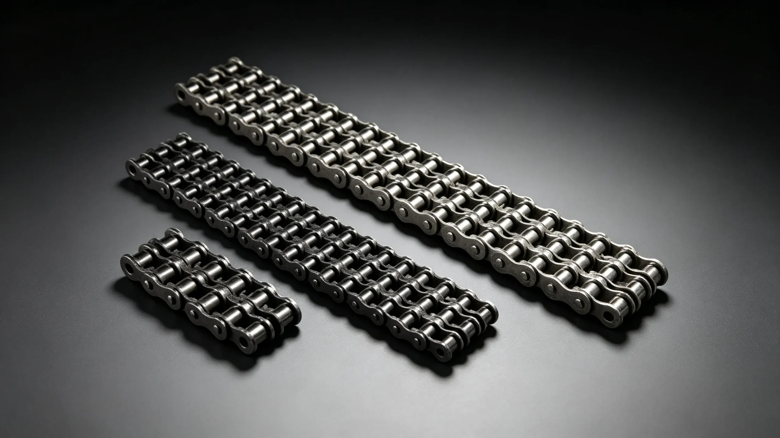
The connecting link is the most statistically common failure location in conveyor roller chain — more chain failures occur at or adjacent to the connecting link than at any other single location in the chain loop. The reason is structural: the connecting link is the weakest link in the assembly by design, rated at 85 to 95 percent of the chain breaking load, and it is the location most likely to have been assembled incorrectly.
In conveyor applications specifically, connecting link failure often follows a period of chain skip events — when the chain skips a tooth under load, the impulse load at that moment falls on whatever link is at the sprocket engagement arc. If the connecting link happens to be in that position during a skip event, the impulse load can exceed the spring clip retention force and dislodge the clip. Even without skip events, vibration in long conveyor spans gradually works a spring clip out of its groove if the clip was not fully seated at installation or if the open end of the clip faces the direction of chain travel.
Failure Location 2: The Drive Sprocket Engagement Zone
The section of chain that wraps around the drive sprocket — the high-load side of the chain — accumulates more fatigue cycles at higher stress than any other section of the loop. With each revolution of the drive sprocket, each link in the wrap arc is loaded to the full chain pull on the tight side, then unloaded as it transitions to the slack side. This high-amplitude cyclic loading is concentrated in the tight-side wrap arc, and over thousands of sprocket revolutions it generates fatigue damage at the pin-hole locations in the link plates.
The tight-side wrap arc is also where roller impact against sprocket teeth occurs at each engagement — particularly when the chain has elongated and the rollers are seating higher on the tooth face. Impact loading at this location adds to the fatigue damage from the tensile cycling, compounding the rate of plate fatigue crack initiation.
Failure Location 3: Transition From Loaded to Unloaded Strand
The section of chain transitioning from the tight (loaded) side to the slack (unloaded) side — at the drive sprocket exit point — experiences a sudden reduction in tension on each revolution. This tension release causes a small but rapid plate relaxation movement that, over millions of cycles in a continuously running conveyor, can cause fretting between the pin and bushing at this specific location. The fretting corrosion products (fine iron oxide particles) are abrasive and further accelerate wear at these specific links.
This failure pattern is most visible in long conveyors where the same links repeatedly transition at the same sprocket position — which happens when the chain loop length is an exact multiple of the sprocket tooth pitch. Deliberate use of an odd number of links (even in a drive that could accommodate an even count) spreads the transition stress across different links on each revolution, reducing the concentration of fatigue damage at specific positions.

Failure Location 4: Mid-Span Catenary Sag Points
On long conveyor runs, the chain sags under its own weight between the drive and tail sprockets — the catenary (hanging) section on the return strand. The maximum bending stress in the chain occurs at the lowest point of this sag and at the support points where the chain transitions from straight to curved. In conveyors with worn or incorrectly positioned return strand guides or support rails, the chain can develop a kink at a guide edge — a stress concentration that causes rapid fatigue cracking at that specific location.
Return strand chains that rest on fixed guides or rails also experience fretting wear on the outer roller and plate surfaces where they contact the guide. While this external plate wear does not directly cause failure by itself, it introduces surface irregularities that act as fatigue initiation sites under the cyclic loading of the drive. Ensure return strand guides are smooth, correctly positioned, and made from a material softer than the chain (nylon or HDPE) to minimise this wear mechanism.
Failure Location 5: Tail Sprocket Re-Engagement
At the tail (non-driven) end of a conveyor, the chain wraps around the tail sprocket and transitions from the return strand to the loaded carrying strand. This re-engagement event involves a sudden application of tension to the chain as it begins to carry the conveyor load. In conveyors with steep inclines, heavy loads, or long carrying spans, this tension step is significant — particularly during start-up when acceleration loads are added to the steady-state running tension.
Tail sprocket re-engagement failures are more common in inclined conveyors than horizontal conveyors, and more common at start-up than during steady-state running. If failures consistently occur in the tail sprocket section, review the conveyor start-up procedure — a soft-start variable frequency drive (VFD) that gradually accelerates the conveyor can dramatically reduce the tensile stress spike at start-up and extend chain life at this location.
| Failure Location | Typical Failure Mode | Primary Cause | Preventive Action |
|---|---|---|---|
| Connecting link | Spring clip ejection; plate fatigue | Wrong clip orientation; vibration; shock loading | Use cottered link; verify clip orientation at inspection |
| Drive sprocket wrap arc | Link plate fatigue cracking at pin holes | High cyclic loading from chain pull; impact from elongated chain | Replace at 3% elongation; use heavy series or sawtooth plate for variable loads |
| Tight-to-slack transition | Fretting corrosion at pin-bushing interface | Repeated rapid tension change — especially with exact-multiple loop length | Use odd link count; specify O-ring chain if contamination is also present |
| Mid-span catenary | Kink fatigue at guide contact points | Worn or misaligned return strand guides | Maintain smooth guide surfaces; use nylon or HDPE guides |
| Tail sprocket re-engagement | Plate fatigue and pin fracture on inclined conveyors | Start-up tension spike from acceleration load | Install VFD soft-start; check tail sprocket alignment |
The Role of Elongation Measurement in Predicting Failure Location
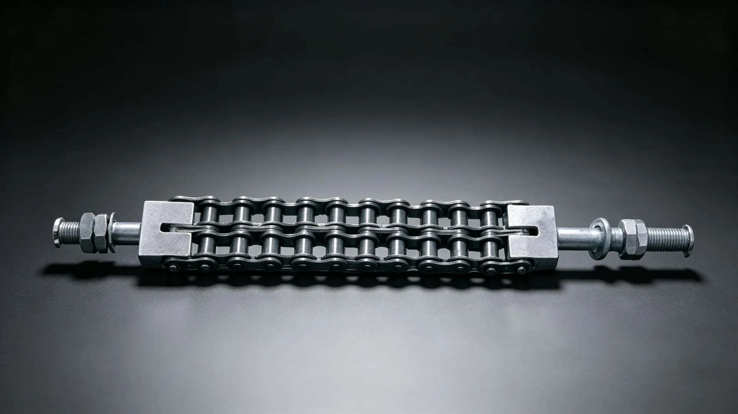
Systematic elongation measurement across the full chain loop — measuring at multiple points around the loop rather than only at one convenient location — reveals non-uniform wear patterns that indicate local overloading or lubrication problems at specific positions. A section of chain that shows higher elongation than the average for the loop has been experiencing higher load or less effective lubrication at that location. The failure is most likely to occur in or adjacent to this high-elongation section.
For critical production conveyors, establishing a per-section elongation map at each scheduled maintenance interval provides early warning of developing failure concentrations. Sections approaching 2.5 percent elongation can be identified and replaced before the overall loop average reaches the 3 percent threshold — preventing in-service failures while optimising the use of remaining chain life in lower-wear sections.
EverPower Roller Chains Australia provides conveyor roller chain in ANSI and ISO series, alongside technical support for conveyor chain failure analysis and maintenance programme optimisation. Contact our Sydney team to discuss your conveyor chain failure pattern and the appropriate chain specification for your application.
+61 2 9708 3322 | [email protected] | 27 Harley Crescent, Condell Park NSW 2201