
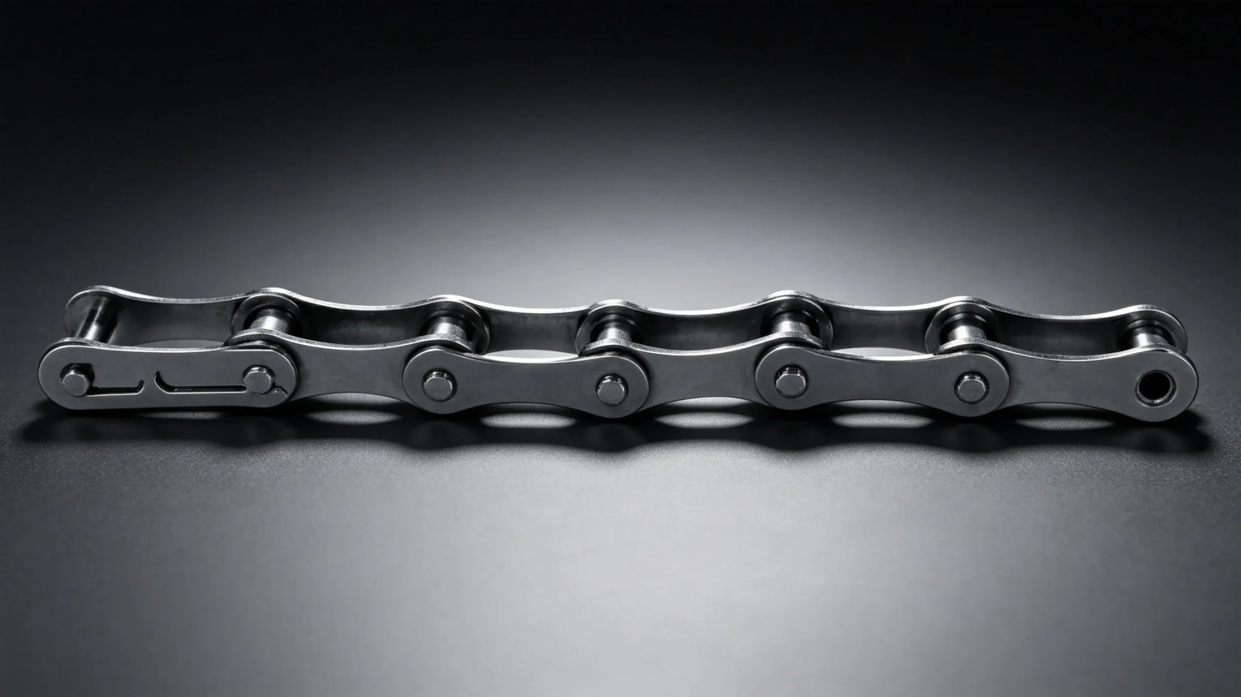
Chain size selection for a conveyor drive is one of those engineering tasks that looks straightforward but has several layers of complexity once you move beyond the obvious starting point of “what pitch fits the existing sprocket.” Getting it right means understanding the relationship between chain speed, load, pitch, and service factor — and working through those relationships systematically rather than defaulting to whatever was there before. This guide walks through the complete roller chain size selection process for conveyor systems, from the initial load calculation through to final pitch and strand count specification.
Step 1: Define the Conveyor Load and Drive Requirements
Before any roller chain dimension can be specified, four parameters must be established: the total chain pull (the tangential force at the drive sprocket), the chain speed required for the conveyor, the operating hours per day, and the nature of the loading — smooth and continuous, moderately variable, or heavily variable with shock peaks. Each of these inputs affects the final chain size selection, and estimating any of them incorrectly will lead to either an under-specified chain that fails prematurely or an over-specified chain that wastes budget.
Chain pull in a conveyor is the sum of several force components: the force required to move the payload (product weight multiplied by the friction coefficient of the conveyor surface), the dead weight of the chain and carrying structure on the loaded strand (also multiplied by friction), the force to raise material if the conveyor is inclined, and any additional resistances from scrapers, side guides, or return strand sagging. For horizontal conveyors with a well-designed return system, chain pull is approximately 15 to 25 percent of total payload weight for typical conveyor coefficients of friction in the range of 0.2 to 0.35.
Step 2: Apply the Service Factor
The service factor adjusts the calculated chain pull upward to account for the dynamic loading conditions that the roller chain will experience in practice. ANSI B29.1 defines three service factor categories:
| Loading Type | Service Factor | Typical Conveyor Applications |
|---|---|---|
| Smooth — uniform load, steady speed, no shock | 1.0 | Uniform product on flat belt conveyors, grain augers, low-speed material transfer |
| Moderate shock — slight variation, moderate starts | 1.3 | Bucket elevators, screw conveyors, moderate incline conveyors with variable product density |
| Heavy shock — significant variation, frequent starts under full load | 1.5–1.7 | Vibrating conveyors, apron conveyors, mining belt feeders, conveyors with frequent jam/restart cycles |
Multiply the calculated chain pull by the service factor to obtain the design chain pull. This is the figure that drives the pitch and strand count calculation. For a conveyor with a calculated chain pull of 8.5 kN operating with moderate shock (service factor 1.3), the design chain pull is 8.5 x 1.3 = 11.05 kN.
Step 3: Match Pitch to Speed and Load Using Rating Tables
Roller chain power rating tables provided by manufacturers (and reproduced in ANSI B29.1) list the rated power per strand for each pitch size at a range of driving sprocket speeds and tooth counts. Divide the shaft power by the design chain pull speed product to obtain required horsepower, then cross-reference the rating table to find the smallest pitch that meets the requirement at the available sprocket speed with at least 17 teeth on the small sprocket.
| ANSI Chain | Pitch (mm) | Typical Max Working Load Simplex (kN) | Common Conveyor Application |
|---|---|---|---|
| ANSI 40 | 12.70 | 3.5–5.0 | Light product conveyors, packaging lines, low-load transfer |
| ANSI 50 | 15.875 | 5.5–8.0 | Medium conveyors, general industrial transfer, small elevators |
| ANSI 60 | 19.05 | 8.5–12.0 | Agricultural conveyors, medium industrial, grain handling |
| ANSI 80 | 25.40 | 14.0–20.0 | Heavy industrial conveyors, mining feeders, bulk material handling |
| ANSI 100 | 31.75 | 22.0–32.0 | Heavy mining conveyors, quarry equipment, high-load industrial |
| ANSI 120 | 38.10 | 32.0–45.0 | Very heavy mining, steel plant conveyors, extreme duty |
Step 4: Consider Chain Speed and Its Effect on Selection
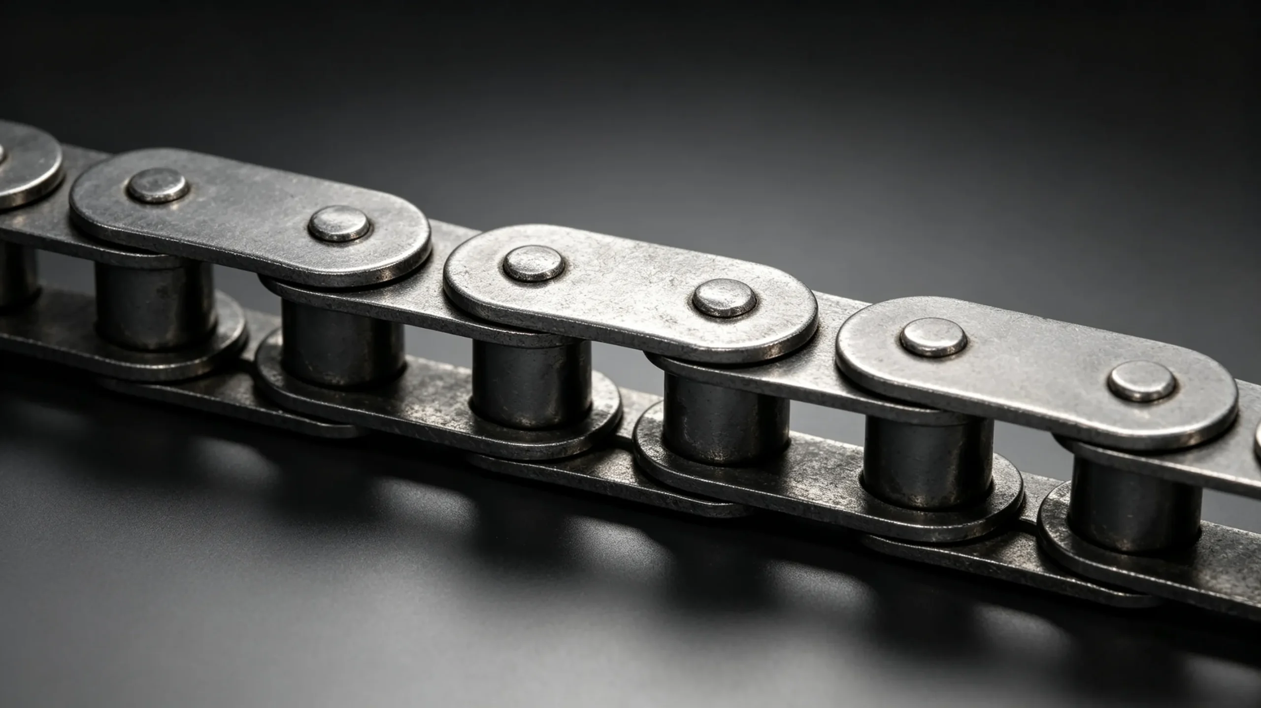
Chain speed directly affects which pitch is appropriate. At higher speeds, the impact force when each roller engages a sprocket tooth increases with the square of velocity — doubling chain speed quadruples the impact energy per engagement. This makes large-pitch chain increasingly unsuitable at high speeds, and pushes designers toward smaller pitch with multiple strands to maintain load capacity while keeping speed within the pitch-specific limit.
The general guideline for conveyor roller chain: keep chain speed below 1.5 m/s for double pitch chain, below 3 m/s for ANSI 80 and larger, and below 5 to 6 m/s for ANSI 60 in well-lubricated industrial drives. Agricultural conveyors typically operate below 2 m/s, where ANSI 60 and 80 are well within their speed limits.
Step 5: Single Strand vs Multiple Strands
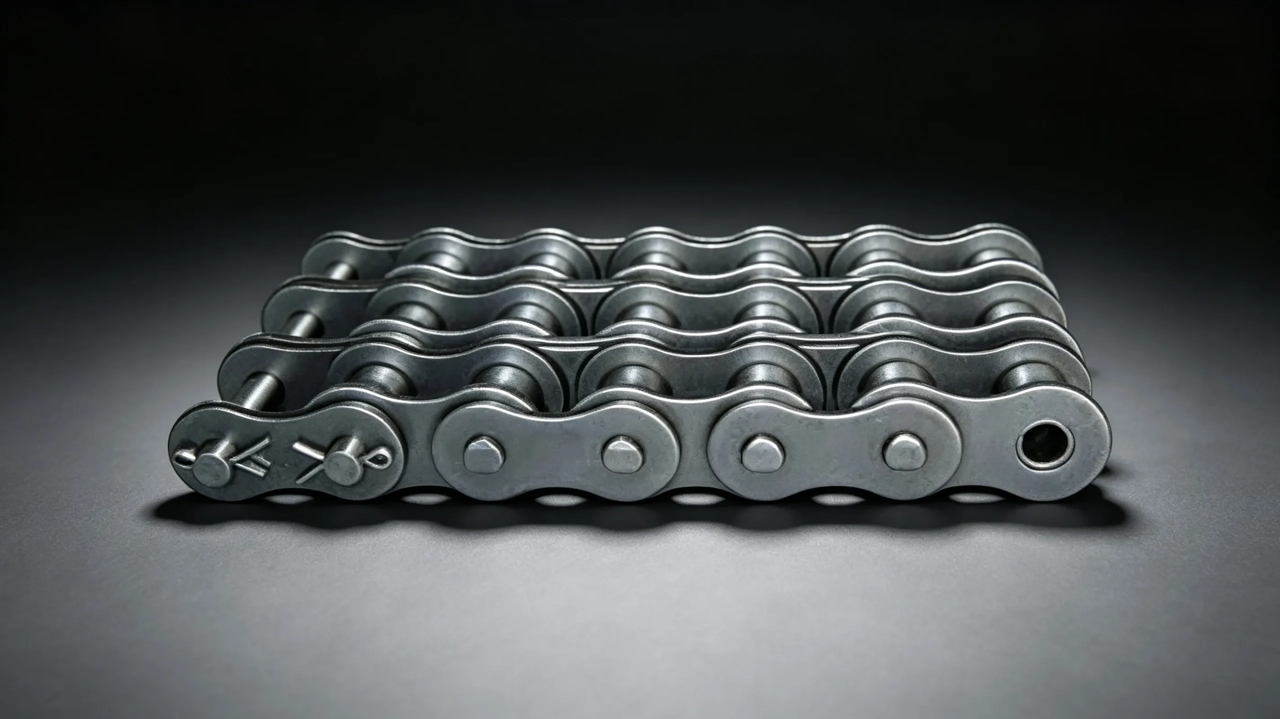
If the required working load exceeds the simplex (single strand) rating for the pitch you have identified, the options are to move to the next larger pitch or add a second strand (duplex). Adding a strand is often preferable at moderate to high speeds because it keeps the pitch small — which means smaller sprockets, quieter operation, and better resistance to chordal action. The duplex working load is approximately 1.75 times the simplex rating for the same pitch.
For conveyor roller chain applications, duplex is preferred over moving to a larger pitch when: the drive speed is above 1.5 m/s, sprocket diameter is constrained by shaft centreline requirements, or the conveyor is long and the chain weight must be minimised. Single-strand chain is preferred when: the conveyor is short and slow, sprocket width is constrained, or the drive is a simple single-point drive with straightforward maintenance access.
Step 6: Verify Elongation Life Against Required Service Interval
A final check in the roller chain size selection process is to verify that the specified chain will achieve the required service interval before reaching its elongation replacement threshold. Manufacturers publish wear life charts or formulae relating chain life (in metres of travel or operating hours) to the ratio of operating load to rated load. If the calculated life is shorter than the required maintenance interval, either increase chain size, improve lubrication provisions, or specify a sealed chain type (O-ring or self-lubricating) to extend wear life.
For a typical agricultural conveyor chain running 8 hours per day at moderate load with correct lubrication, ANSI 60 chain should achieve 2,000 to 3,500 hours before reaching 3 percent elongation. For a mining conveyor running 24 hours per day at 70 percent of rated load, the same chain pitch may last only 1,200 to 1,800 hours — which may or may not be acceptable depending on the maintenance schedule at that site.
EverPower Roller Chains Australia can assist with conveyor roller chain specification for new drives and replacements. Send us your conveyor load, speed, and operating hours data and our Sydney team will recommend the correct pitch, strand count, and chain type for your application.
+61 2 9708 3322 | [email protected] | 27 Harley Crescent, Condell Park NSW 2201