
Breaking strength is the figure most frequently cited when engineers and procurement managers compare roller chains, yet it is also the figure most frequently misapplied. The breaking strength of ANSI 60 roller chain tells you the load at which the chain will catastrophically fail under a static tensile test — it does not tell you the load at which you should operate the chain. The gap between these two figures, and the correct way to use breaking strength data in drive design, is what this article covers in detail.
The Breaking Strength of ANSI 60 Chain: The Baseline Figure
Per ANSI B29.1, the minimum breaking load for standard simplex ANSI No. 60 roller chain is 31.3 kN (approximately 3,190 kgf or 7,040 lbf). This is the minimum tensile load at which the chain must fracture when tested in a static tensile pull to destruction on a calibrated test machine. Quality manufacturers routinely achieve 10 to 20 percent above this minimum; 31.3 kN is the floor, not the expected value.
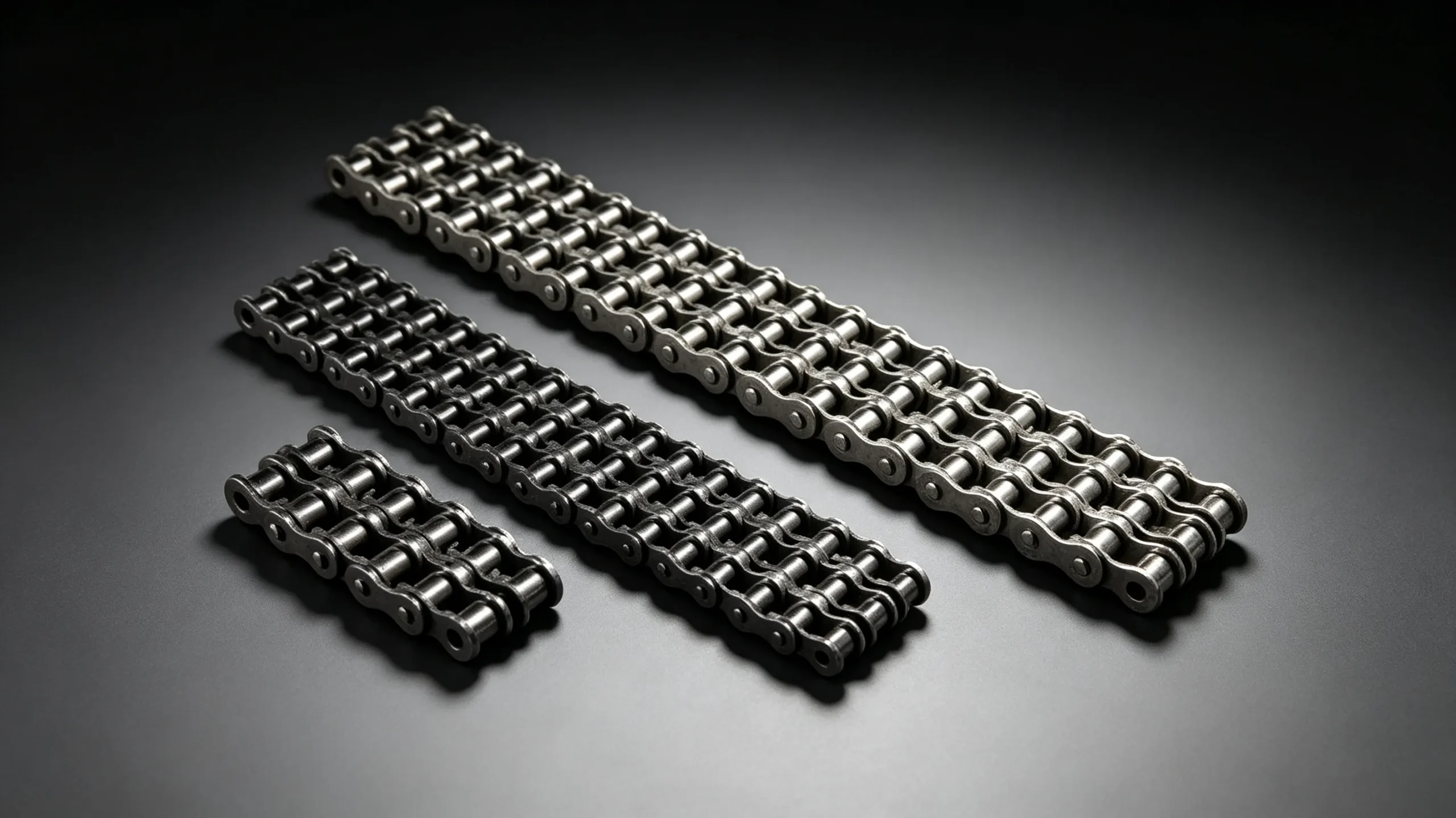
For heavy series ANSI 60H, the minimum breaking load increases to 42.3 kN — approximately 35 percent higher than standard. For duplex ANSI 60-2, the combined breaking load of both strands is approximately 54.5 kN (31.3 x 1.74 strand efficiency factor). For triplex ANSI 60-3, the combined breaking load reaches approximately 77.8 kN (31.3 x 2.49).
| Chain Type | Min. Breaking Load (kN) | Min. Breaking Load (kgf) | Min. Breaking Load (lbf) |
|---|---|---|---|
| ANSI 60 Simplex | 31.3 | 3,192 | 7,039 |
| ANSI 60H Simplex (Heavy) | 42.3 | 4,313 | 9,504 |
| ANSI 60-2 Duplex | ~54.5 | ~5,556 | ~12,238 |
| ANSI 60-3 Triplex | ~77.8 | ~7,934 | ~17,490 |
Breaking Strength vs Working Load: A Critical Distinction
Operating a chain anywhere near its breaking load would result in failure within a very small number of load cycles. Breaking strength is a static, one-time failure measurement. The maximum recommended working load for continuous operation is a fraction of breaking strength, determined by applying a safety factor and a service factor that together account for dynamic loads, impact loading, chain elongation, and fatigue life requirements.
For ANSI 60 simplex chain running a smooth drive at moderate speed (service factor 1.0), the maximum working load is approximately 8.7 kN — roughly 28 percent of breaking load. For a moderate shock application (service factor 1.3), the permissible working load reduces to approximately 6.7 kN. For severe shock (service factor 1.7), the permissible working load is approximately 5.1 kN. The safety factor embedded in these figures is typically 7 to 12 for dynamic chain drives, compared to 3 to 5 for static structural applications.
How Chain Speed Affects Working Load
Breaking strength is a speed-independent figure measured in a static test. Working load, however, is strongly speed-dependent in practice. As chain speed increases, dynamic loading from chordal action, vibration, and the inertia of chain links on the sprocket entry arc adds to the static transmitted load. ANSI B29.1 power rating tables account for this by providing rated power values at specific speed and sprocket tooth combinations — the rated power for ANSI 60 chain running on a 17-tooth sprocket at 500 RPM is different from the rated power at 1,500 RPM.
The practical implication: do not use breaking strength alone to size a chain for a high-speed drive. Use the manufacturer power rating tables, which already incorporate the speed-dependent dynamic load factors. Breaking strength becomes directly relevant only for low-speed, high-torque applications where the ratio of peak load to mean load is the dominant design driver, such as hoist chains and low-speed conveyor chains.
Factors That Reduce Effective Breaking Strength in Service
Connecting Link Strength
The connecting link (master link) joining the chain loop is typically rated at 90 to 95 percent of the chain breaking load when correctly assembled with a cotter pin. A spring clip connecting link is rated at 80 to 85 percent in most manufacturer specifications. This means the connecting link is almost always the weakest point in the chain loop — a fact that explains why chain failures at the connecting link are so common. For critical drives, use cotter pin connecting links and verify assembly at every chain replacement.
Side Wear and Plate Fatigue
A chain in service accumulates side plate wear and fatigue damage progressively. The effective breaking load of a worn chain is lower than the published minimum for new chain. There is no reliable non-destructive way to measure the residual breaking strength of a worn chain in the field — which is why elongation measurement and replacement at the 3 percent threshold is the correct maintenance strategy, rather than waiting for visible plate damage or actual fracture.
Corrosion and Environmental Degradation
Surface corrosion on carbon steel chain reduces the effective cross-sectional area of the link plates and introduces surface pitting that acts as a fatigue crack initiation site. A severely corroded chain may retain only 60 to 70 percent of its original breaking load. For outdoor agricultural applications or marine environments, stainless steel chain or regular re-lubrication with a corrosion-inhibiting oil is essential to maintain rated breaking strength throughout the service life.

Comparing ANSI 60 Breaking Strength to Adjacent Chain Sizes
| ANSI Chain | Pitch (mm) | Min. Break Load (kN) | Ratio vs ANSI 60 |
|---|---|---|---|
| ANSI 50 | 15.875 | 21.8 | 0.70x |
| ANSI 60 | 19.05 | 31.3 | 1.00x (baseline) |
| ANSI 60H | 19.05 | 42.3 | 1.35x |
| ANSI 80 | 25.40 | 55.6 | 1.78x |
| ANSI 100 | 31.75 | 87.0 | 2.78x |
This table illustrates why pitch selection matters so much: moving from ANSI 60 to ANSI 80 increases breaking load by 78 percent, but also increases the pitch from 19.05 mm to 25.40 mm — meaning the sprockets must be larger and the maximum permissible chain speed is lower. The correct approach is to calculate required working load first, then work backwards through safety and service factors to determine the required breaking load, then match this to the appropriate chain size.
Practical Guide: Calculating Required Chain for a Known Load
To determine whether ANSI 60 chain is suitable for a specific application, work through this sequence. First, measure or calculate the maximum chain pull in kilonewtons — this is the tangential force at the pitch circle of the smaller sprocket. Second, apply the service factor from ANSI B29.1 (1.0 for smooth, 1.3 for moderate shock, 1.7 for heavy shock). Multiply maximum chain pull by service factor. Third, apply a safety factor of at least 7 to obtain the required minimum breaking load. If the result is below 31.3 kN, ANSI 60 simplex is sufficient. If it falls between 31.3 and 42.3 kN, use ANSI 60H. If it exceeds 42.3 kN at ANSI 60 pitch, move to duplex or increase pitch to ANSI 80.
EverPower Roller Chains Australia supplies ANSI 60, 60H, and 60-2 chain from stock in Sydney. Our team can assist with working load calculations and chain specification for drives in agricultural, mining, and industrial applications across Australia.
+61 2 9708 3322 | [email protected] | 27 Harley Crescent, Condell Park NSW 2201