
EverPower Roller Chains Australia — Technical Knowledge Base
A complete technical guide covering construction, operating principles, standard classifications, identification logic, and real-world performance data — written for engineers, procurement managers, and maintenance teams.
📅 August 2026
📍 EverPower Roller Chains Australia Pty Ltd
⏰ 12 min read
Roller chains are among the most widely used mechanical power transmission components on the planet. From agricultural balers and mining conveyors to food processing lines and construction equipment, they operate quietly in the background of almost every industrial sector. Yet despite this ubiquity, the internal mechanics of a roller chain — how the geometry transfers load, why pitch matters, and what actually fails first — remain poorly understood outside specialist circles. This article covers all of it.
1. The Basic Definition: What Exactly Is a Roller Chain?
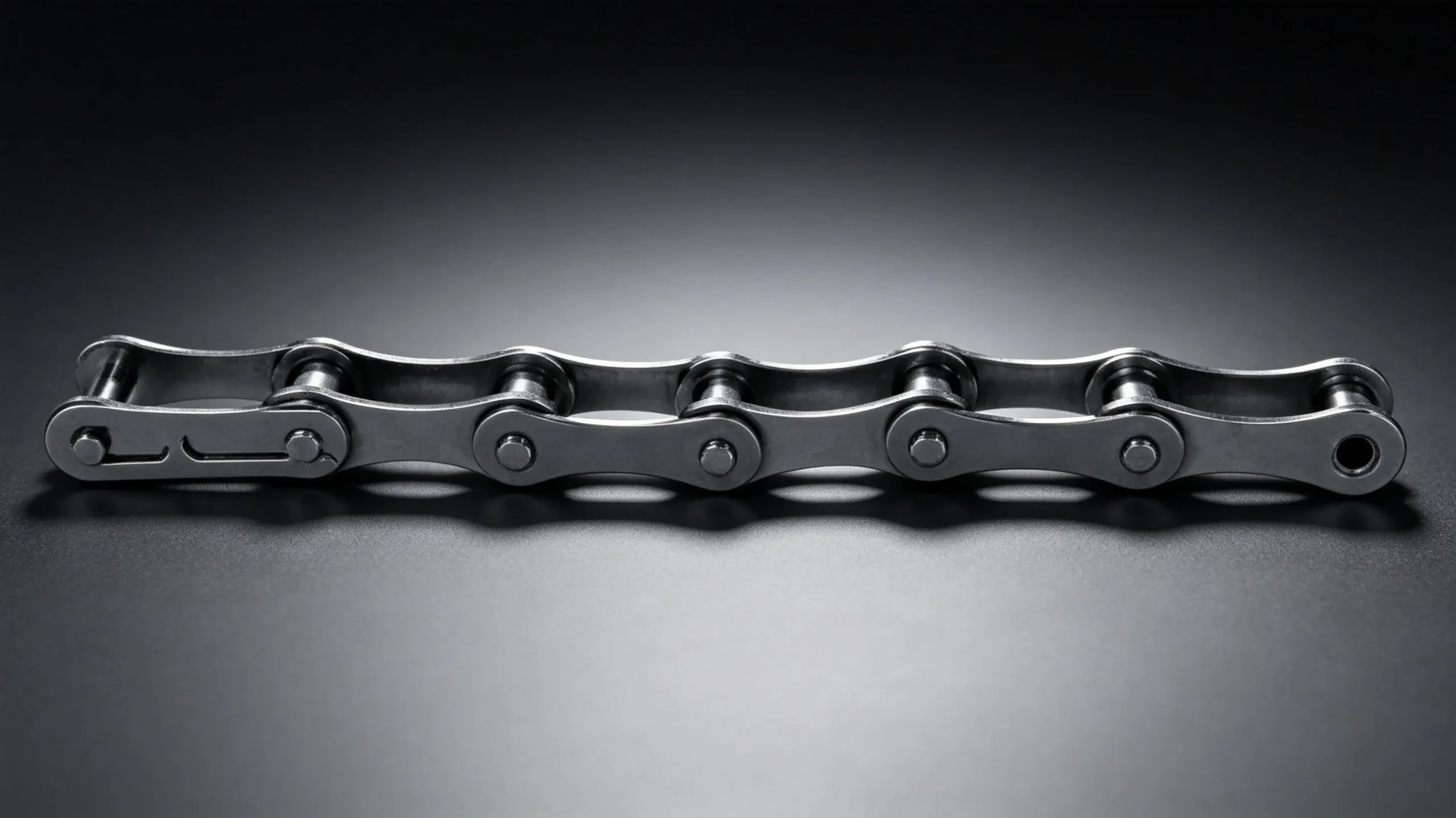
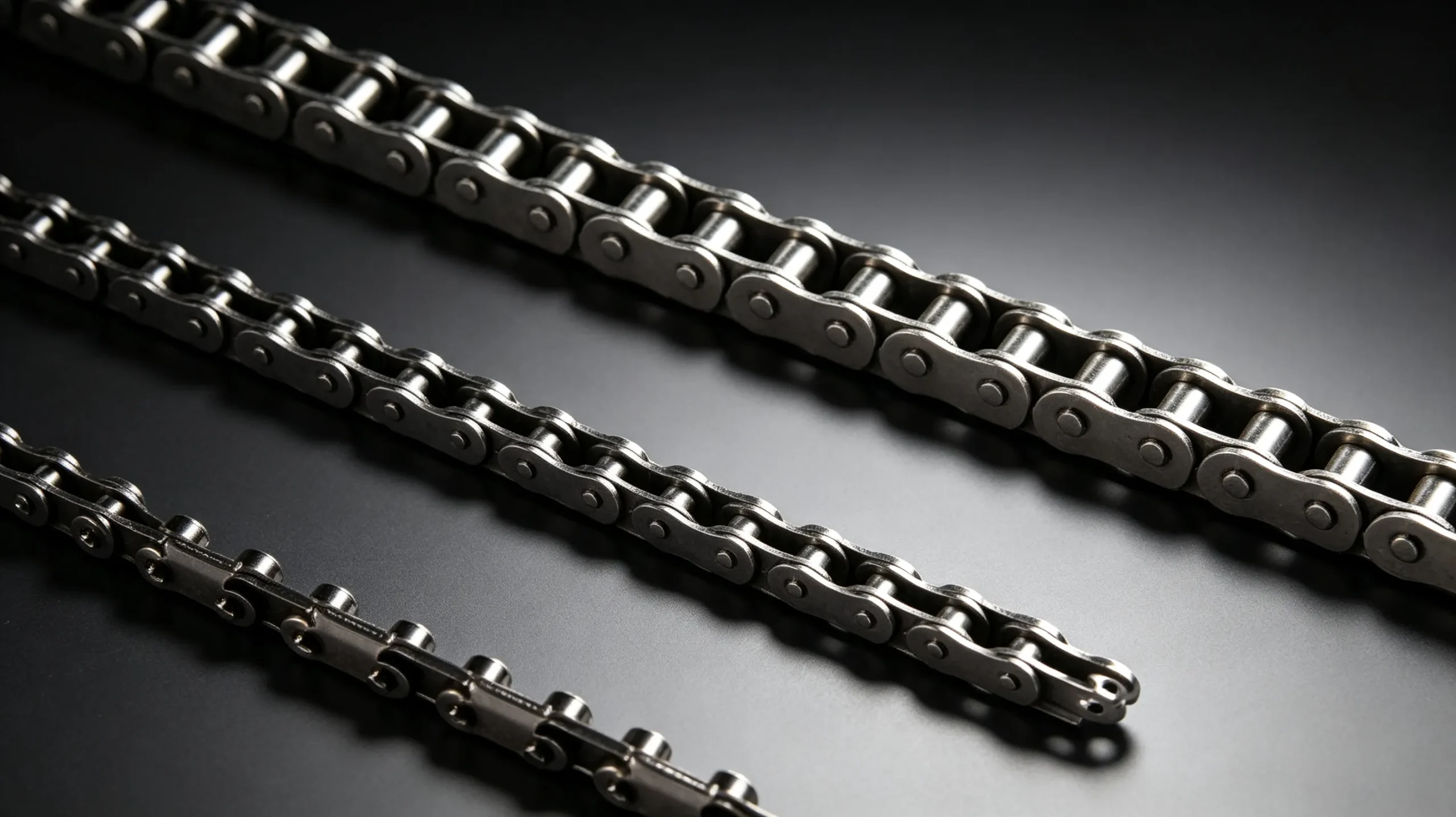
A roller chain is a type of chain drive used to transmit mechanical power between two rotating sprockets. Unlike a simple link chain, it incorporates a free-rolling cylindrical element — the roller — that sits between each pair of inner plates and reduces friction against sprocket teeth during engagement. This single design feature is what separates roller chains from bushing chains, and it is largely responsible for the roller chain extraordinary efficiency and load-bearing longevity.
The concept dates to Hans Renold 1879 patent in Manchester, England, where the bushed roller chain replaced earlier open-link designs used on bicycles and textile machinery. Within two decades, the format had been standardised for industrial machinery and adopted globally. Today, the roller chain fundamental architecture remains almost identical to that 1879 original — a testament to how well the geometry works.
In modern industrial settings, roller chains are specified under two primary standards: ANSI B29.1 (used predominantly in North America and Australia) and ISO 606 / BS 228 (common across Europe and much of Asia). Both standards define pitch, roller diameter, inner width, and breaking load for each chain size — ensuring interchangeability within a standard but not across them.
2. Anatomy of a Roller Chain: Every Component and Its Function
Understanding what a roller chain is made of is inseparable from understanding why it performs the way it does. There are five primary components in every standard roller chain assembly, and each one plays a specific mechanical role.
2.1 Inner and Outer Link Plates
The side plates are stamped from medium-carbon or alloy steel, then heat-treated to achieve the correct combination of tensile strength and fatigue resistance. Inner plates (also called inner link plates) carry the bushings; outer plates (pin link plates) carry the pins. The figure-eight profile is not aesthetic — the waisted shape reduces weight while keeping cross-section area at the pin holes, where stress concentrations are highest. Heavy series chains use thicker plates with wider waists; standard series chains use proportionally lighter plates for applications where weight and centre-to-centre distance are constrained.
2.2 Pins and Bushings
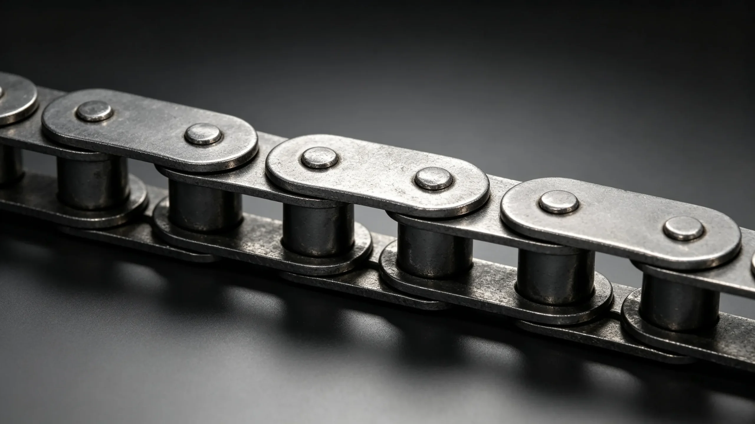
The pin is the primary load-bearing element during bending. It is press-fitted into the outer plates and rotates relative to the bushing during chain articulation. Pins are typically case-hardened to 58–62 HRC on the surface with a tough core to resist impact loading. The bushing is press-fitted into the inner plates and provides a running surface for the roller. The pin-bushing interface is where the majority of wear in a poorly lubricated chain actually occurs — not at the roller-sprocket interface as many assume.
2.3 The Roller
The roller sits freely on the outside of the bushing and is the component that makes direct contact with the sprocket tooth. When a link engages a sprocket, the roller rolls up the tooth face rather than sliding — this rolling action is responsible for the chain mechanical efficiency of 97–99% under lubricated conditions, one of the highest figures of any power transmission method. Rollers are hardened to approximately 40–50 HRC to resist tooth-impact wear, and their diameter is sized to match the sprocket tooth gap geometry precisely.
Roller Chain Component Summary
| Component | Material | Hardness | Primary Failure Mode |
|---|---|---|---|
| Link Plates | Medium-carbon steel | 30–40 HRC | Fatigue cracking at pin holes |
| Pins | Alloy steel, case-hardened | 58–62 HRC surface | Abrasive wear, bending fatigue |
| Bushings | Alloy steel, case-hardened | 55–60 HRC surface | Pin-bore wear (lubrication-critical) |
| Rollers | Medium-carbon steel | 40–50 HRC | Impact spalling, cracking |
| Connecting Links | Matching plate steel | Same as outer plate | Spring clip/cotter failure, improper assembly |
3. How a Roller Chain Actually Transfers Power
The operating principle of an industrial roller chain is deceptively simple: the chain wraps around a driving sprocket (attached to a motor or engine) and a driven sprocket (attached to the shaft that needs to be turned). As the driving sprocket rotates, its teeth push against the chain rollers, pulling the chain and thereby rotating the driven sprocket. The velocity ratio is determined by the tooth count of each sprocket, exactly as with a gear pair, but without the constraint of fixed centre distance.
3.1 The Chordal Action Effect
One phenomenon that engineers must account for is chordal action, also called polygonal action. Because the chain links are rigid and the sprocket is circular, the chain centre traces a polygon rather than a true circle during engagement. This produces a cyclical variation in chain velocity and tension — typically increasing with fewer sprocket teeth. A sprocket with 17 teeth or more keeps chordal action below 3%, which is acceptable for most applications. Sprockets with fewer than 11 teeth amplify this effect significantly and should be avoided in high-speed drives.
3.2 Tight Side vs. Slack Side Tension
Under load, one span of the chain carries the working tension (tight side) while the return span carries only the pretension (slack side). The difference in tension between these two spans is what actually transmits power. Correct initial tension is critical: too tight and bearing loads increase needlessly; too slack and the chain can skip or jump teeth under sudden load. The standard recommendation for most horizontal drives is a total sag of approximately 2–3% of the centre distance on the slack side.
4. Roller Chain Pitch: The Single Most Important Dimension
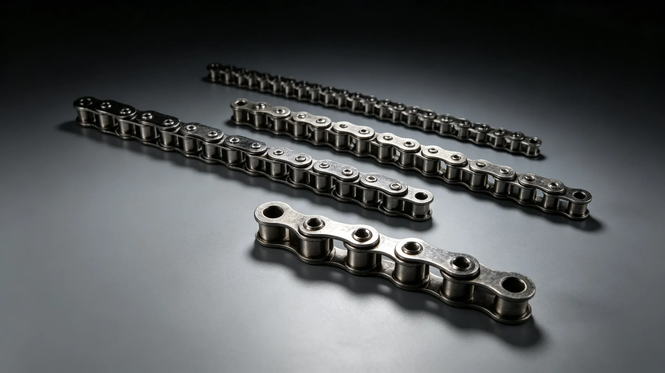
Pitch is the centre-to-centre distance between adjacent pin holes, and it is the defining dimension of any roller chain. Every other parameter — roller diameter, inner width, plate thickness, and breaking load — is derived from the pitch in a fixed ratio. This is why chain sizes are often referred to simply by pitch in millimetres (e.g., 12.7 mm, 15.875 mm, 25.4 mm) or by ANSI chain numbers (40, 50, 60, 80) where the first digits represent pitch in eighths of an inch.
Selecting the correct pitch involves balancing several factors simultaneously: the power to be transmitted, the speed of the drive, the desired centre distance, and the available sprocket sizes. Smaller pitch chains run more quietly and suit higher speeds; larger pitch chains carry more load per strand but generate more chordal action at equivalent speeds.
| ANSI No. | Pitch (mm) | Roller Dia. (mm) | Min. Break Load (kN) | Typical Application |
|---|---|---|---|---|
| ANSI 25 | 6.35 | 3.30 | 3.1 | Light instrumentation |
| ANSI 40 | 12.70 | 7.92 | 14.1 | General light machinery |
| ANSI 50 | 15.875 | 10.16 | 21.8 | Medium machinery, packaging |
| ANSI 60 | 19.05 | 11.91 | 31.3 | Agricultural machinery, conveyors |
| ANSI 80 | 25.40 | 15.88 | 55.6 | Heavy industrial drives |
| ANSI 100 | 31.75 | 19.05 | 87.0 | Mining, steel plant |
| ANSI 120 | 38.10 | 22.23 | 125.0 | Heavy mining, quarrying |
Data per ANSI B29.1 simplex standard. Heavy series chains carry approximately 30% higher breaking loads at equivalent pitch.
5. Types of Roller Chain: From Simplex to Sawtooth Plate
The term “roller chain” covers a broad family. Choosing the right variant is as important as chooseing the right pitch. Here are the main types encountered in Australian industrial procurement:
5.1 Simplex, Duplex, and Triplex
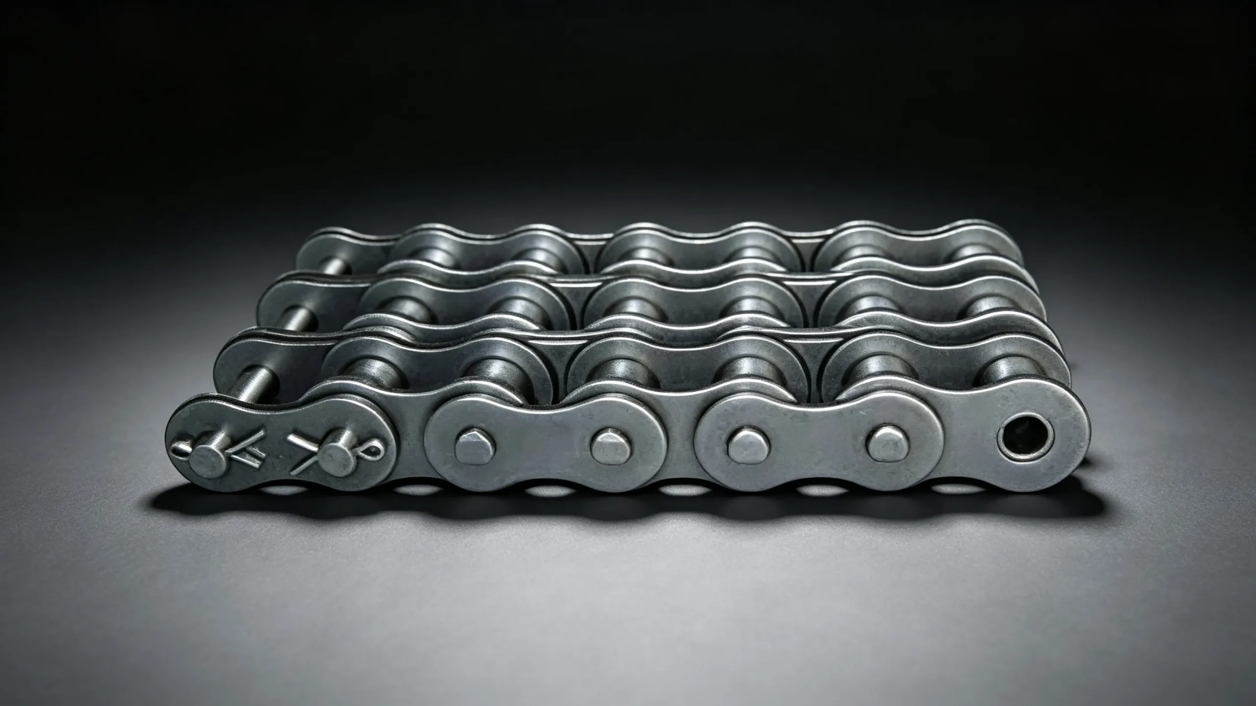
A simplex (single-strand) chain is the baseline. Duplex adds a second strand in parallel, roughly doubling the load capacity without changing the pitch. Triplex adds a third strand. Multi-strand chains are used where a larger pitch would produce too much chordal action at the required speed, or where the drive geometry does not permit a wider single chain. Load capacity scales approximately as 1.7× per additional strand (not 2.0×, due to load distribution imperfection across strands).
5.2 Heavy Series vs. Standard Series
Heavy series chains use the same pitch as standard chains but have thicker link plates and larger pins. They are not always a direct plug-in replacement because the wider inner link width may require sprocket face width to be checked. Heavy series chains are the correct choice for shock-load environments — crusher drives, baler plunger drives, and shaker conveyors — where standard chains fail prematurely at the pin hole fatigue point.
5.3 Sawtooth Plate Roller Chain
The sawtooth plate roller chain — the signature product of this website — replaces the standard flat link plate profile with a serrated edge geometry. The sawtooth profile increases the plate surface area and introduces stress redistribution around the pin hole, which laboratory fatigue testing has shown can extend plate fatigue life by 20–40% under cyclic loading conditions compared to flat plate equivalents. This makes it particularly well suited to combine harvester drives, hay baler feeds, and other agricultural machinery where loading is highly variable and replacement is expensive during harvest season.
5.4 Stainless Steel and Specialty Chains
For food processing, pharmaceutical, and marine environments, stainless steel roller chain (304 or 316 grade) provides corrosion resistance that carbon steel cannot match. The trade-off is reduced tensile strength — typically 70–80% of equivalent carbon steel chain — and higher cost. Self-lubricating chains (sintered bushings impregnated with oil) and O-ring chains (sealed lubricant pockets) address the lubrication challenge in dusty or wash-down environments where conventional re-lubrication is impractical.
6. Roller Chain Wear and Elongation: The Real Performance Indicator
Roller chains do not wear by stretching in the metallurgical sense — the steel plates and pins do not plastically deform under normal operating loads. What actually happens is wear elongation: material is gradually removed from the pin-bushing contact surfaces, increasing the effective pitch of each link by a small amount. As links accumulate this wear, the total chain length increases measurably, and the chain begins to ride higher on sprocket teeth rather than seating at the root diameter.
6.1 The 3% Elongation Rule
The widely accepted replacement threshold is 3% elongation of the measured chain length over the manufacturer nominal pitch. At this point, chain engagement geometry has deteriorated sufficiently that tooth load distribution becomes uneven, accelerating both chain and sprocket wear exponentially. For conveyor chains, many maintenance standards recommend the more conservative threshold of 1.5% elongation to protect sprockets on long, expensive conveyor systems.
Measurement is straightforward: count a fixed number of pitches (typically 25–30 links) and compare the measured length to the nominal (pitch × number of links). A 50-link section of ANSI 60 chain nominally measures 955 mm (50 × 19.05 mm). If that same section measures 984 mm or more in service, replacement is overdue.
6.2 Factors That Accelerate Wear
Lubrication failure is the dominant accelerant — a chain running dry can wear to 3% elongation in one-tenth the time of a properly lubricated equivalent. Contamination with abrasive particles (sand, grain dust, mineral fines) introduces three-body abrasion into the pin-bushing interface and accelerates wear similarly. Misalignment between drive and driven sprocket forces lateral loads onto the chain that the side plates were not designed to carry. Finally, operating at loads exceeding the recommended working load pushes peak contact pressures beyond the oil film capacity, causing metal-to-metal contact even with adequate lubricant supply.
7. How Roller Chains Compare to Alternative Power Transmission Methods
Engineers chooseing a drive system for a new machine or a retrofit regularly compare roller chains against V-belt drives, flat belt drives, and gear drives. The trade-offs are real and context-specific.
| Factor | Roller Chain | V-Belt | Gear Drive |
|---|---|---|---|
| Efficiency | 97–99% | 92–96% | 95–99% |
| Shock Load Tolerance | High | Medium | Low–Medium |
| Centre Distance Flexibility | High | High | Fixed |
| Slip | None (positive) | Possible | None |
| Initial Cost | Medium | Low | High |
| Maintenance Requirements | Lubrication, tension | Tension, replacement | Oil level, seals |
Roller chains offer the best combination of positive engagement, efficiency, shock tolerance, and centre distance flexibility for heavy industrial and agricultural applications. The main advantage belt drives hold is lower noise and vibration at very high speeds — a factor that only becomes decisive above approximately 10 m/s chain velocity for most drive designs.
8. Lubrication: The Most Impactful Maintenance Decision You Will Make
No aspect of roller chain performance is more influenced by maintenance decisions than lubrication. The difference in service life between a properly lubricated chain and a dry-running chain can be a factor of 10 or more in identical operating conditions. This is not an exaggeration — field studies in agricultural machinery have documented chains running without lubrication wearing to replacement threshold in under 200 hours, while identical chains with correct lubrication exceeded 2,000 hours before reaching 3% elongation.
8.1 Lubrication Types and Application Methods
Manual application with a brush or oil can is acceptable for slow-moving chains (below 0.5 m/s) in accessible locations, applied to the inner link area during a routine shift inspection. Drip lubrication — a mechanical dispenser metering oil onto the chain at a controlled rate — suits speeds up to approximately 4 m/s. Bath lubrication (chain running through an oil reservoir on the slack side) and force-feed lubrication (oil pumped directly to the chain through a nozzle) are required for high-speed, high-load, or enclosed drives.
8.2 Lubricant Selection
Use a mineral oil of ISO VG 68–150 for most industrial roller chain applications. Avoid grease: it does not penetrate the pin-bushing clearance and actually traps abrasive particles on the outside surface. In food processing, an NSF H1 rated food-grade oil is mandatory. In outdoor agricultural applications where wash-off is a concern, a tackified (adhesive) oil or chain-specific spray lubricant with penetrating solvent carrier is preferable to standard oil, as it resists centrifugal throw-off better during operation.
9. Selecting the Right Roller Chain: A Practical Decision Framework
For engineers and procurement teams sourcing chain for a new or replacement application, the following framework reduces the chooseion to a manageable sequence of decisions:
Define the Power and Speed
Calculate shaft power (kW) and driving sprocket RPM. Apply a service factor (1.0–1.7) based on load smoothness and daily hours of operation before entering chooseion tables.
Choose Pitch and Strands
Use manufacturer power rating tables to identify the smallest pitch that handles the design load at the operating speed. If pitch becomes too large, switch to duplex or triplex rather than increasing pitch further.
Specify Sprocket Teeth
Aim for at least 17 teeth on the small sprocket to control chordal action. Tooth ratio should not exceed 7:1 for most applications. Always replace sprockets when installing new chain if existing sprockets show hook-shaped teeth.
Check Centre Distance and Chain Length
Calculate the required chain length in links using the centre distance formula. Prefer even link counts to avoid offset (half) links. Adjust centre distance to accommodate the even-link length.
Specify Material and Type
Standard carbon steel for most dry or lubricated indoor drives. Stainless for corrosive environments. Sawtooth plate for high shock-load applications. O-ring or self-lube for dusty environments where re-lubrication is infrequent.
Plan the Maintenance Regime
Document lubrication type, interval, and elongation check schedule before installation. The most common reason for premature chain failure is not poor product quality — it is a maintenance programme that was never defined.
Featured Product
EverPower Sawtooth Plate Roller Chain — ANSI Series
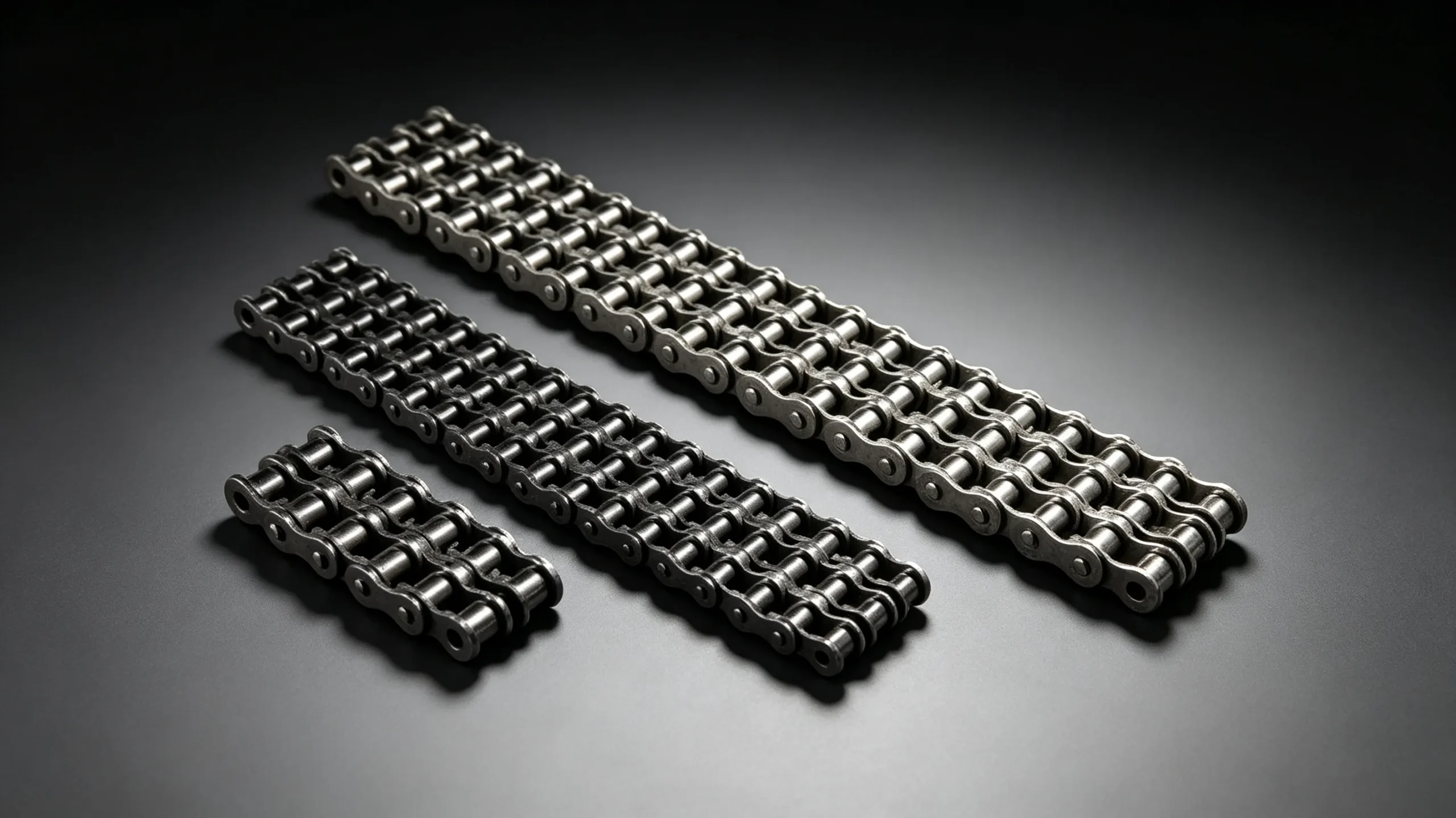
Manufactured to ANSI B29.1 standards, the EverPower sawtooth plate series is available in pitch sizes from ANSI 40 through ANSI 120 in both simplex and duplex configurations. The serrated plate profile extends fatigue life by up to 40% in variable-load drive conditions — making it the preferred choice for agricultural machinery, hay balers, and conveyor drives operating through harvest-season continuous shifts.
ISO 606 Available
Custom Lengths
Bulk OEM Pricing
Frequently Asked Questions
Common questions about roller chain construction, performance, and specification.
Need Help Selecting the Right Roller Chain?
EverPower Roller Chains Australia supplies ANSI and ISO series industrial roller chains to customers across New South Wales, Queensland, Victoria, and beyond. Our technical team can cross-reference your existing chain by size, standard, and application — and advise on whether the sawtooth plate upgrade is appropriate for your drive conditions.