Description
Overview: The Fundamental Roller Chain
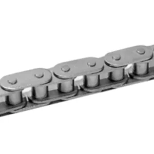
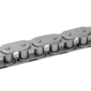
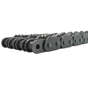
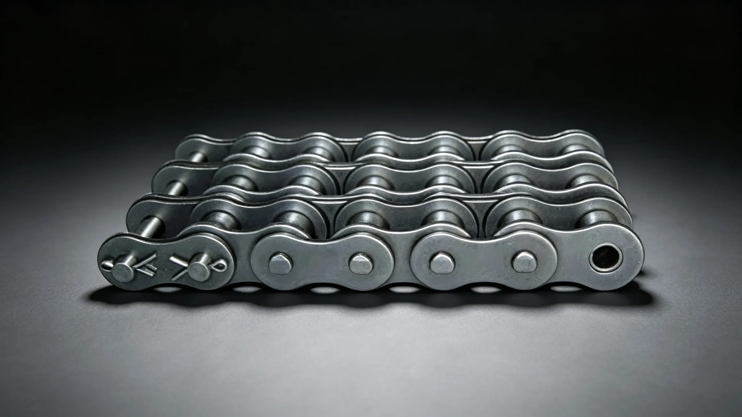
The simple roller chain — sometimes called simplex or single-strand roller chain — is the starting point from which all other roller chain variants are derived. Its design has remained essentially unchanged for over a century: outer link plates connected to inner link plates through hardened pins, with a hardened bushing at each pin-inner-plate joint and a freely rotating roller over each bushing. This arrangement is mechanically elegant in its simplicity: the roller reduces the engagement friction between chain and sprocket to rolling contact rather than sliding, which is the core reason roller chains transmit power so efficiently at high speeds compared to bush chains or link chain alternatives.
Despite the apparent simplicity, the manufacturing precision required to produce a high-quality roller chain is substantial. Link plate pitch holes must be punched to tolerances of ±0.01mm to maintain consistent pitch across the full chain length — pitch variation accumulates across each link and, over a long chain, manifests as dynamic load variation that generates vibration and accelerates wear. Pin case hardening must reach a controlled depth without over-hardening the core, which would make the pin brittle under shock loading. Roller hardness must balance between too-soft (which deforms under sprocket impact) and too-hard (which causes fatigue cracking in high-shock applications). These requirements are why the performance difference between quality and economy roller chains is immediately visible in service life measurements.
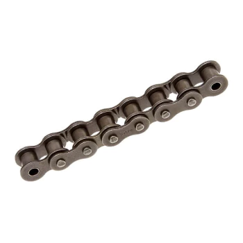
Standard simplex roller chains — ANSI #25 through #240, ISO 04B through 48B
ANSI Standard Roller Chain Specifications
The table below covers the primary ANSI standard simplex roller chain sizes from #25 through #120. These conform to ANSI/ASME B29.1 and are manufactured to the dimensional and tensile specifications of that standard.
| ANSI No. | Pitch P (mm) | Roller Ø d1 (mm) | Inner Width b1 (mm) | Pin Ø d2 (mm) | Plate Depth h2 (mm) | Plate Thick. t (mm) | Q min (kN) | Avg Q0 (kN) | Weight (kg/m) |
|---|---|---|---|---|---|---|---|---|---|
| #25 | 6.350 | 3.30 | 3.18 | 2.31 | 6.00 | 0.76 | 3.33 | 4.1 | 0.09 |
| #35 | 9.525 | 5.08 | 4.77 | 3.58 | 9.00 | 1.27 | 7.78 | 9.8 | 0.28 |
| #40 | 12.700 | 7.95 | 7.85 | 3.96 | 12.00 | 1.52 | 14.10 | 17.0 | 0.61 |
| #50 | 15.875 | 10.16 | 9.40 | 5.08 | 15.09 | 2.03 | 21.80 | 26.3 | 0.92 |
| #60 | 19.050 | 11.91 | 12.57 | 5.94 | 18.00 | 2.39 | 31.30 | 36.9 | 1.44 |
| #80 | 25.400 | 15.88 | 15.75 | 7.92 | 24.00 | 3.18 | 55.60 | 66.7 | 2.49 |
| #100 | 31.750 | 19.05 | 18.90 | 9.53 | 30.00 | 3.96 | 87.50 | 105.0 | 3.73 |
| #120 | 38.100 | 22.23 | 25.22 | 11.10 | 35.70 | 4.78 | 125.60 | 150.3 | 5.81 |
ISO Standard Roller Chain Specifications
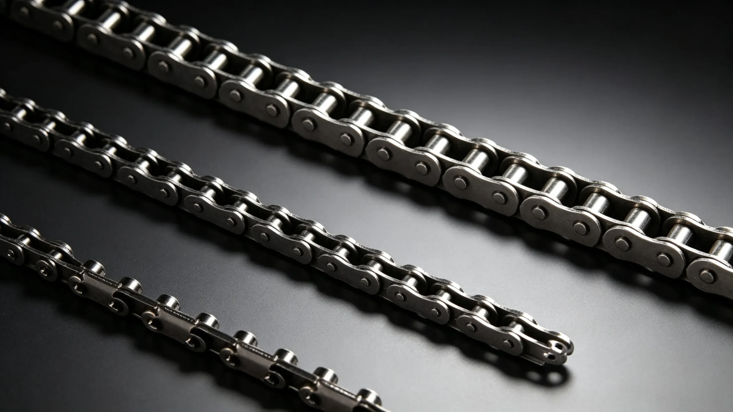
ISO B series simplex chains covering 04B through 24B — the standard specification for European-designed machinery.
| ISO No. | Pitch P (mm) | Roller Ø (mm) | Inner Width (mm) | Pin Ø (mm) | Plate Depth (mm) | Q min (kN) | Weight (kg/m) |
|---|---|---|---|---|---|---|---|
| 04B-1 | 6.000 | 4.00 | 2.80 | 1.85 | 5.00 | 3.2 | 0.11 |
| 06B-1 | 9.525 | 6.35 | 5.72 | 3.28 | 8.20 | 9.0 | 0.41 |
| 08B-1 | 12.700 | 8.51 | 7.75 | 4.45 | 11.81 | 18.0 | 0.69 |
| 10B-1 | 15.875 | 10.16 | 9.65 | 5.08 | 14.70 | 22.2 | 0.93 |
| 12B-1 | 19.050 | 12.07 | 11.68 | 5.72 | 16.13 | 29.0 | 1.15 |
| 16B-1 | 25.400 | 15.88 | 17.02 | 8.28 | 21.10 | 60.0 | 2.71 |
| 20B-1 | 31.750 | 19.05 | 19.56 | 10.19 | 26.42 | 95.0 | 3.70 |
| 24B-1 | 38.100 | 25.40 | 25.40 | 14.63 | 33.40 | 160.0 | 7.10 |
Material and Finish Options
Standard carbon steel roller chains — heat-treated alloy steel throughout — cover the vast majority of industrial applications. For environments requiring additional corrosion resistance, surface appearance, or food compliance, three further options are available:
Matching Sprockets for Roller Chains
A roller chain drive performs only as well as the weakest element in the system. Sprockets with worn, incorrectly profiled, or non-matching pitch teeth generate uneven load distribution across the chain links, accelerate both chain and sprocket wear, and can cause the chain to jump teeth at higher speeds. We supply matched sprockets for all ANSI and ISO simplex roller chain sizes in the following configurations: pilot bore (bore to be finished by the customer), finished bore to specified diameter, and taper lock bore for quick-release shaft mounting. Tooth counts from 9 to 114 teeth. Available in carbon steel, case-hardened steel, and cast iron for high-wear positions.
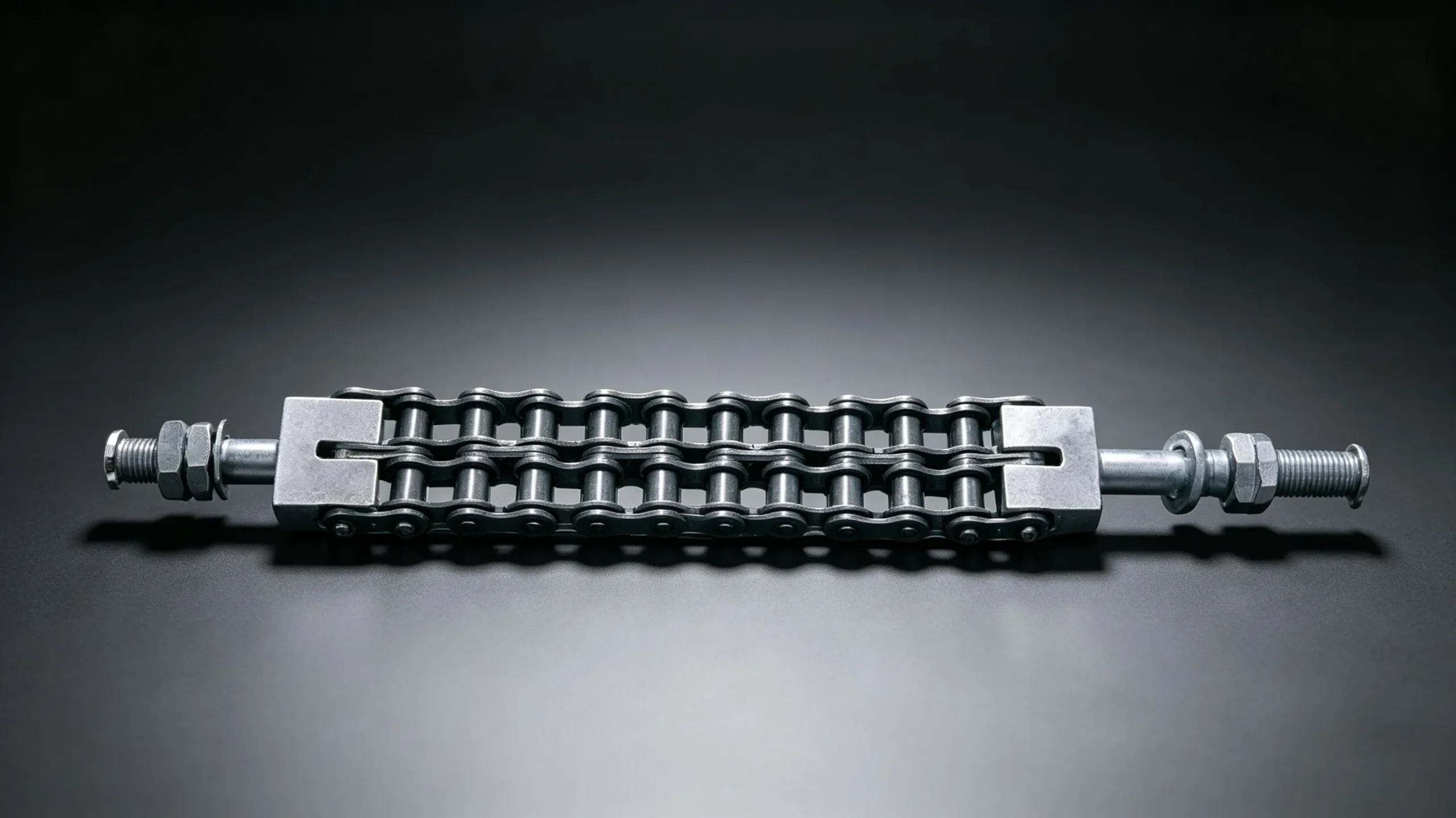
Components and Matching Parts
Customer Reviews
“We use #60 simplex as standard for our conveyor head drives across our facility. The batch-to-batch quality here is noticeably better than the economy chains we were buying previously — pitch tolerance is consistent and the chains don’t develop the erratic elongation pattern we were seeing. We’ve standardised all conveyor purchasing through this supplier.”
“Ordered 16B-1 ISO simplex in stainless steel for our parts washing conveyor. The 316L material and accompanying compliance certificate passed our internal IMDS review without any queries. Delivery was 8 days — faster than the quoted lead time. Will continue ordering for our other wash-down conveyor lines.”
“We needed nickel-plated #50 chains for our packaging conveyor where appearance matters to our customer audit process. The nickel finish is uniform and the chains have shown no rust spots after 10 months in a moderately humid environment. Good value for the specification and the technical sheet was clear and complete.”
Frequently Asked Questions
Get in Touch
Ready to Place Your Order?
Send us your specifications. Standard enquiries receive a full quotation within 2 business days.
For more on chain selection and maintenance, see why roller chain elongation matters and when to replace and what causes roller chain to stretch prematurely.