Description
What Side Bow Chain Does That Standard Chain Cannot
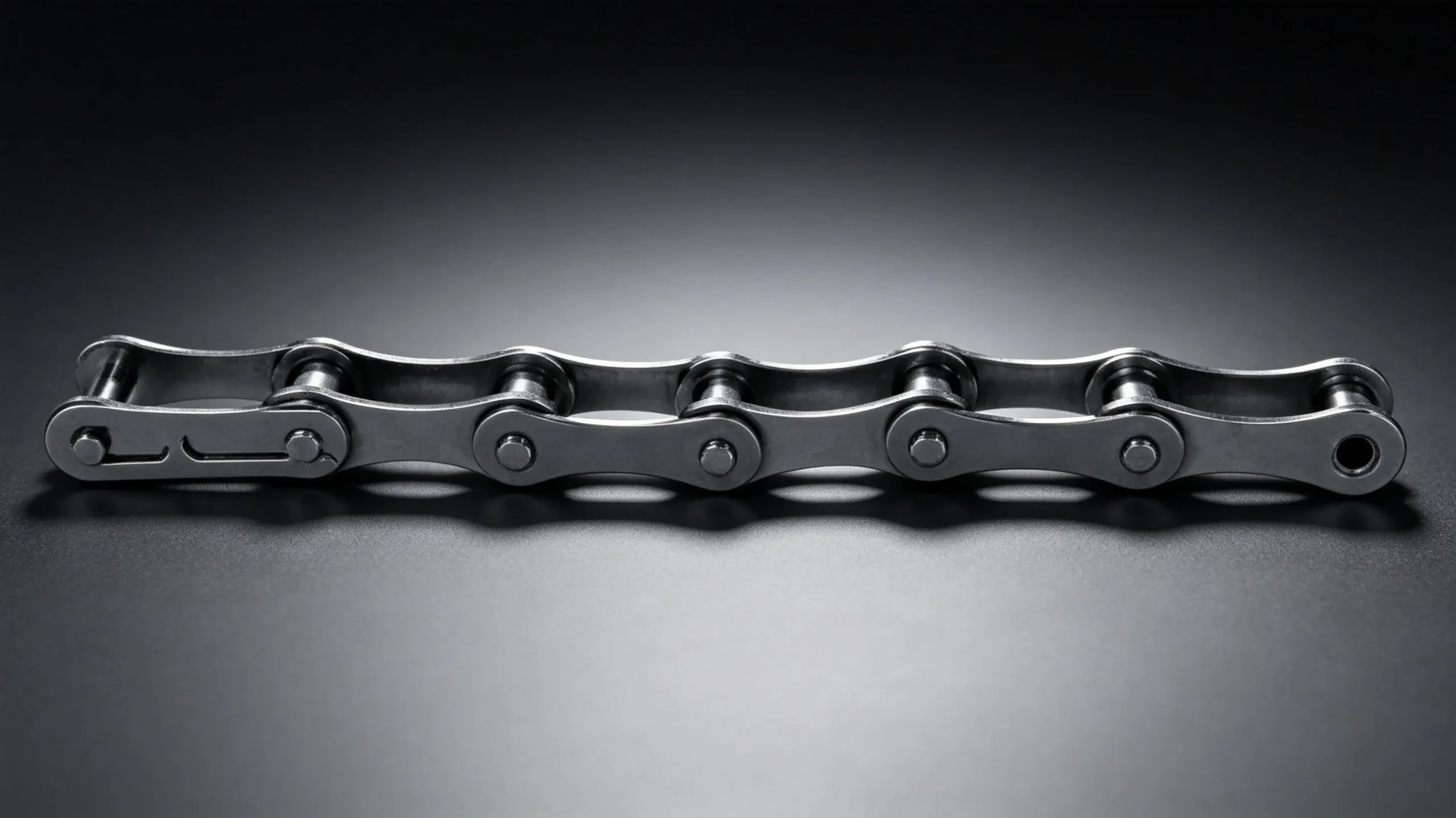
Standard roller chains are rigid in the lateral plane — they articulate freely in the vertical plane of sprocket engagement but cannot flex sideways without generating destructive stress on the link plates. When a conveyor layout requires a horizontal curve, designers using standard chain must either break the conveyor into separate straight sections connected by transfer stations, or use an entirely different conveying medium such as a flat belt or slat conveyor. Side bow chains provide a third option: a roller chain with engineered lateral flexibility that follows a curved path without transfer interruptions, while still engaging standard sprockets at the drive and take-up ends of the curve.
The lateral flexibility is achieved through two modifications to standard roller chain geometry: the pin-bushing diametral clearance is significantly enlarged in the lateral direction compared to standard precision roller chain, and the inner and outer link plates are slightly narrowed to reduce the interference that would otherwise occur when the chain bends sideways. These changes allow the chain to articulate around a horizontal curve radius as tight as 500mm (for the smallest SB sizes) while remaining capable of transmitting meaningful conveying loads along the full length of the curved run. The chain engages standard sprockets at the curve ends without any special tooth form modification.
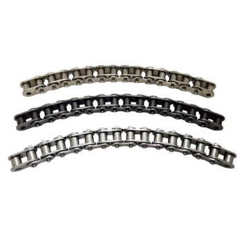
SB Series lateral-flex chains — 40SB through 80SB for curved conveyor and turning station applications
SB Series Specification Table
| Chain No. | Pitch P (mm) | Roller Ø d1 (mm) | Inner Width b1 (mm) | Pin Ø d2 (mm) | Pin Length L (mm) | Plate Depth h2 (mm) | Plate Thick. t (mm) | Q min (kN) | Min Curve Radius (mm) |
|---|---|---|---|---|---|---|---|---|---|
| 40SB | 12.700 | 7.95 | 7.85 | 3.96 | 16.60 | 12.00 | 1.52 | 7.5 | 600 |
| 43SB | 12.700 | 7.95 | 7.85 | 3.96 | 17.00 | 12.00 | 1.52 | 7.5 | 500 |
| 50SB | 15.875 | 10.16 | 9.40 | 5.08 | 20.14 | 15.09 | 2.03 | 11.2 | 700 |
| 60SB | 19.050 | 11.91 | 12.57 | 5.94 | 24.71 | 18.00 | 2.39 | 14.1 | 800 |
| 63SB | 19.050 | 11.91 | 12.57 | 5.94 | 25.10 | 18.00 | 2.39 | 14.1 | 700 |
| 80SB | 25.400 | 15.88 | 15.75 | 7.92 | 30.60 | 24.00 | 3.18 | 22.4 | 900 |
Design Principles of the SB Series
Pin and Bushing Clearance
The enlarged lateral pin-bushing clearance in SB series chains is the primary mechanism enabling lateral flex. In standard precision roller chains, this clearance is minimal — typically 0.05–0.1mm — to maintain pitch accuracy and smooth sprocket engagement. SB series chains increase this clearance to 0.3–0.6mm depending on pitch size, allowing each link joint to rotate slightly in the lateral plane when the chain follows a curve. The cumulative lateral rotation across multiple links is what produces the chain’s ability to follow a curved path. The trade-off is that SB chains have a slightly lower working load rating than standard chains of the same pitch, and their pitch accuracy is reduced — they should not be used for precision indexing applications where exact positioning is required.
Conical Pin Design
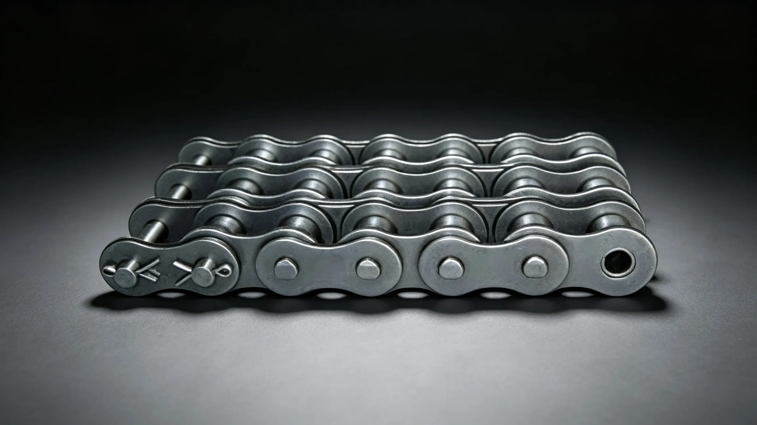
SB series chains use a conical (tapered) pin design rather than the straight cylindrical pin of standard chains. The conical pin automatically centres the bushing within the clearance envelope under load, reducing the asymmetric bushing wear that would otherwise develop if the chain repeatedly navigated the same curved path in one direction. This centring action extends the service life of the pin-bushing interface significantly compared to straight-pin designs used in early lateral-flex chain designs.
Industrial Applications
Load Rating Considerations
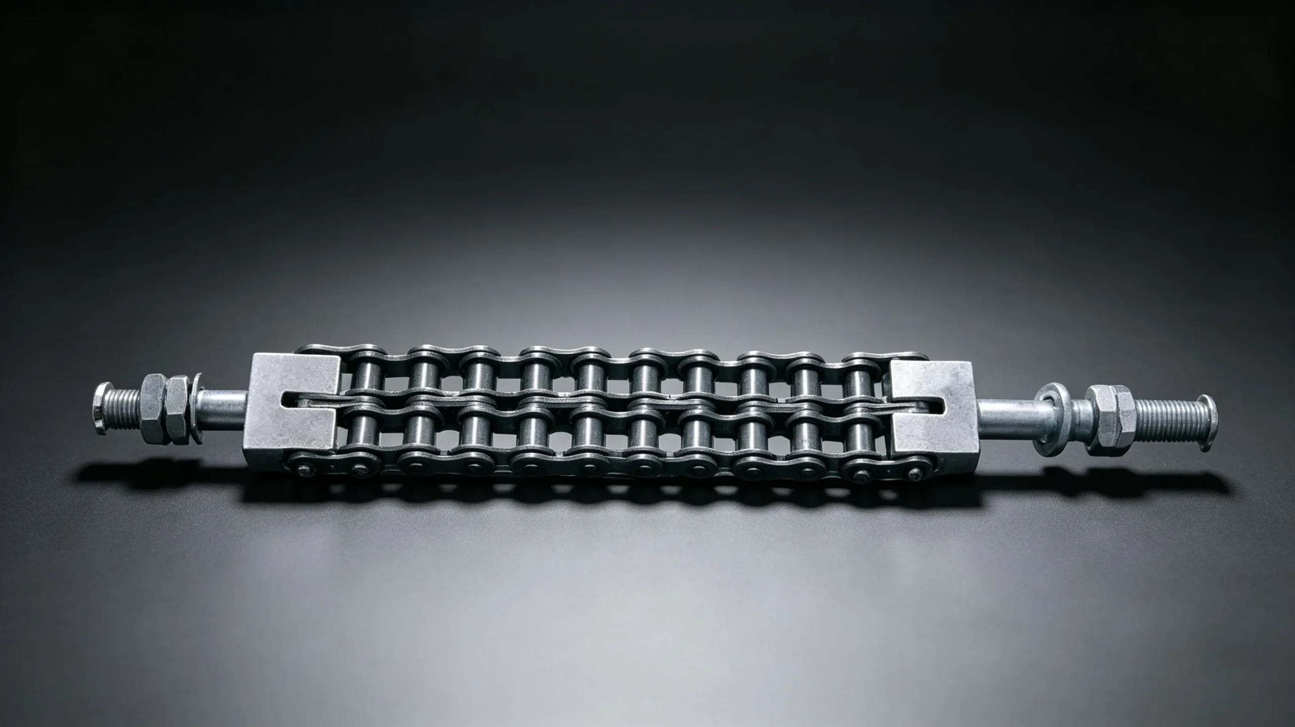
Side bow chains are rated at lower working loads than equivalent-pitch standard chains, reflecting the enlarged pin-bushing clearance that reduces the load-bearing area at each joint. The Q min values in the specification table above are the straight-line tensile ratings — when the chain is operating on a curve, the effective tension in the chain is increased by the centripetal force required to maintain the chain on its curved path, and the chain guide wear force adds to the total lateral load on the pin-bushing interface. For curved sections longer than 1.5m, the centripetal tension increment should be calculated and added to the conveying load before verifying against the chain’s working load limit. Our engineering team provides curve tension calculations on request.
Components and Matching Parts
Customer Reviews
“We design shoe sorter systems for the Nordic parcel market. 40SB and 43SB are our standard specification for divert track assemblies. The minimum curve radius of 500mm for 43SB allows us to fit divert tracks in tight sortation bay layouts that the larger SB sizes couldn’t accommodate. Quality is consistent and lead times are predictable for our project scheduling.”
“Installed 60SB chain on our overhead carcass conveyor renovation. The chain follows our existing rail curves without modification to the overhead structure — a significant project cost saving compared to installing transfer cranes at each curve. Chain has been running 16 months without adjustment.”
“First time using SB chain for a spiral lift project. The engineering team here provided curve tension calculations before we ordered, which gave us confidence in the specification. Installation was straightforward and the chain has performed exactly as the technical data predicted through 18 months of continuous operation.”
Frequently Asked Questions
Get in Touch
Ready to Place Your Order?
Send us your chain specification and annual volume. Standard enquiries receive a quotation within 2 business days.
For more on side bow chain applications see our article on where roller chain is used across industrial machinery sectors.