
A roller chain looks deceptively simple from the outside — a series of linked metal plates joined by pins and carrying rollers at regular intervals. In fact, each link pitch contains five distinct engineered components, each with a specific material specification, heat treatment, dimensional tolerance, and wear surface requirement. Understanding what each component does and why it is specified the way it is provides the foundation for diagnosing failures, evaluating quality, and choosing the right chain for a given application.
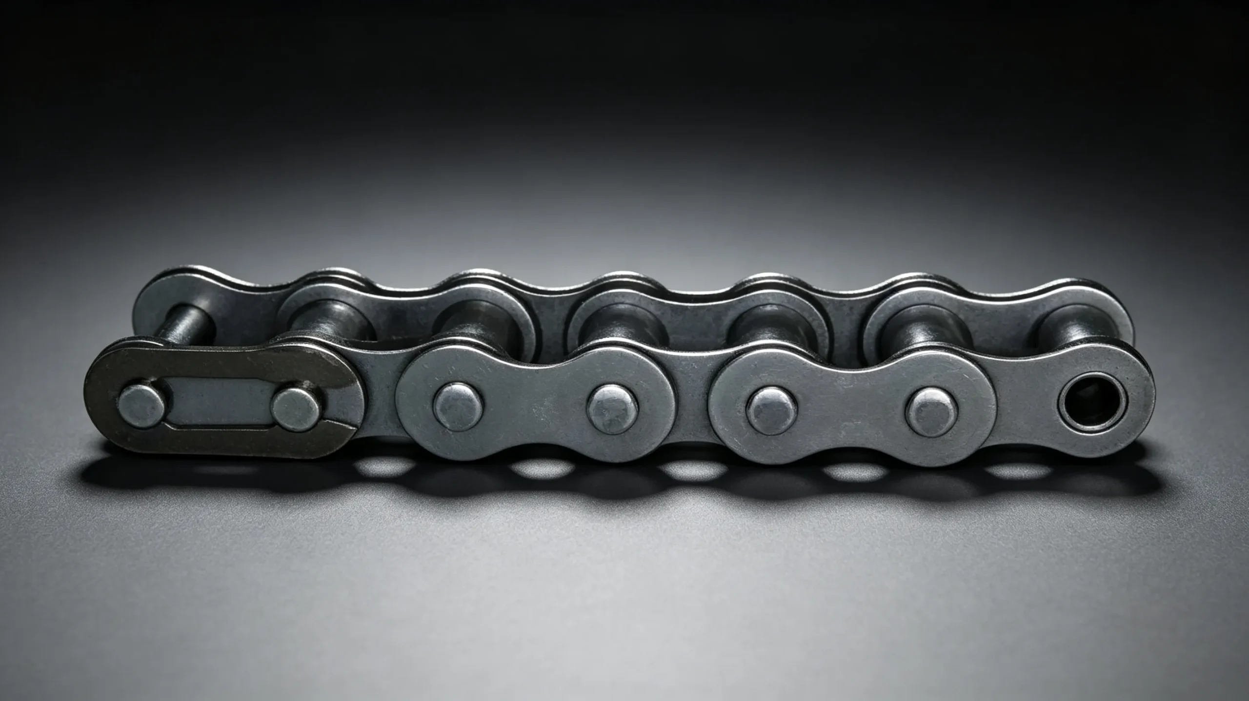
The Five Core Components
Every standard industrial roller chain link pitch contains: two inner link plates, two outer link plates, one pin, one bushing, and one roller. In a assembled chain, inner and outer links alternate — the inner link (with its two inner plates and bushing) nests inside the outer link (with its two outer plates and pin), with the roller sitting outside the bushing between the inner plates. This interleaving is what gives the chain its flexibility in the vertical plane while maintaining rigidity in the lateral plane.
Inner Link Plates
The inner link plates — also called inner plates or bush plates — are the two side plates that carry the bushing. They are stamped from medium-carbon steel sheet, typically 0.35 to 0.45 percent carbon, and heat-treated to a hardness of approximately 30 to 40 HRC. The figure-eight profile reduces plate weight while preserving cross-sectional area at the pin hole locations, where tensile and bending loads are highest during chain articulation.
The bushing is press-fitted into the pin holes of the inner plates with a calculated interference fit — typically 0.02 to 0.05 mm. This interference must be sufficient to prevent the bushing from rotating relative to the inner plate under operating loads, while not so high that it distorts the bushing bore during assembly. For sawtooth plate roller chain, the inner plate profile incorporates the serrated outer edge geometry while maintaining the same pin hole dimensions and bushing bore specification as standard inner plates.
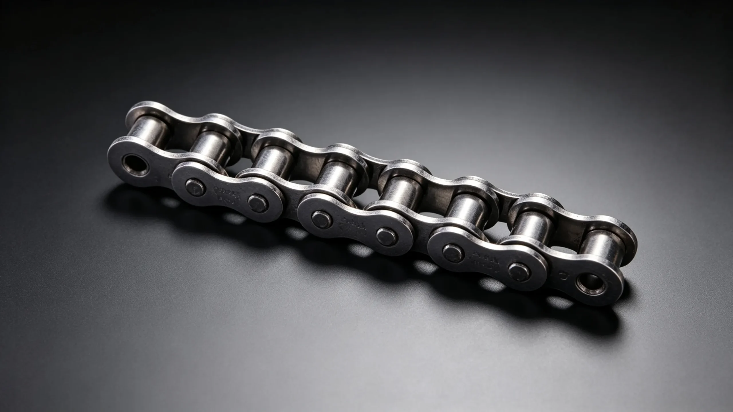
Outer Link Plates
The outer link plates — also called outer plates or pin link plates — carry the pin. They are manufactured from the same steel grade as the inner plates but are typically stamped to a slightly different profile. The outer plate thickness in heavy duty roller chain is greater than in standard chain; the inner plate thickness may also increase in heavy series, but the outer plate increase is generally more pronounced because the pin-to-outer-plate interface is where the maximum bending moment during articulation is concentrated.
In standard chain assembly, the pin is press-fitted into the outer plate holes with an interference fit that retains the pin during operation. In cottered roller chain, the outer plate hole is a clearance fit and retention is provided by the cotter pin rather than by press fit — this is the fundamental distinction between the two types of pin retention used in industrial roller chain.
The Pin
The pin is the primary load-bearing element in the chain, carrying bending and shear loads as the chain transmits torque through the drive. Pins are manufactured from alloy steel — typically a chromium-molybdenum or nickel-chromium alloy — and are case-hardened by carburising or carbonitriding to achieve a surface hardness of 58 to 62 HRC with a tough, ductile core of 30 to 45 HRC. This combination of hard surface and tough core provides both wear resistance at the pin-bushing interface and fatigue resistance against the bending loads during articulation.
Pin diameter is scaled in fixed proportion to chain pitch — approximately 46 percent of pitch for standard ANSI chains. A longer pin span (as in duplex or triplex chain) introduces a higher bending moment for the same transmitted load, which is why multi-strand roller chain power ratings do not scale linearly with strand count.
| Component | Material | Hardness | Key Function | Primary Failure Mode |
|---|---|---|---|---|
| Inner Plate | Medium-carbon steel | 30–40 HRC | Carries bushing; transmits link tension | Fatigue crack at pin hole |
| Outer Plate | Medium-carbon steel | 30–40 HRC | Carries pin; transmits link tension | Fatigue crack at pin hole |
| Pin | Alloy steel, case-hardened | 58–62 HRC surface / 30–45 HRC core | Transmits shear and bending between links | Abrasive wear of surface; bending fatigue |
| Bushing | Alloy steel, case-hardened | 55–60 HRC surface / 25–35 HRC core | Provides running surface for pin and roller | Bore wear from pin; outer wear from roller |
| Roller | Medium-carbon steel | 40–50 HRC | Engages sprocket tooth; rolls to reduce friction | Impact spalling; crack from tooth shock |
The Bushing
The bushing is press-fitted into the inner plate holes and provides two distinct running surfaces: the inner bore surface, which runs against the pin, and the outer cylindrical surface, which provides the running surface for the roller. The bushing is the most wear-critical component in the chain: it absorbs wear from the pin on its inner surface while also wearing against the roller on its outer surface.
Bushing inner bore wear is the mechanism behind roller chain elongation — as the bore wears larger, the pin centre-to-pin centre distance increases, elongating the chain pitch. Bushing outer surface wear is less commonly the limiting factor but becomes significant in high-speed drives where roller slip against the bushing is high. For self-lubricating roller chain, the bushing is manufactured from sintered porous metal impregnated with oil, providing internal lubrication to the pin-bushing interface without external oil application.
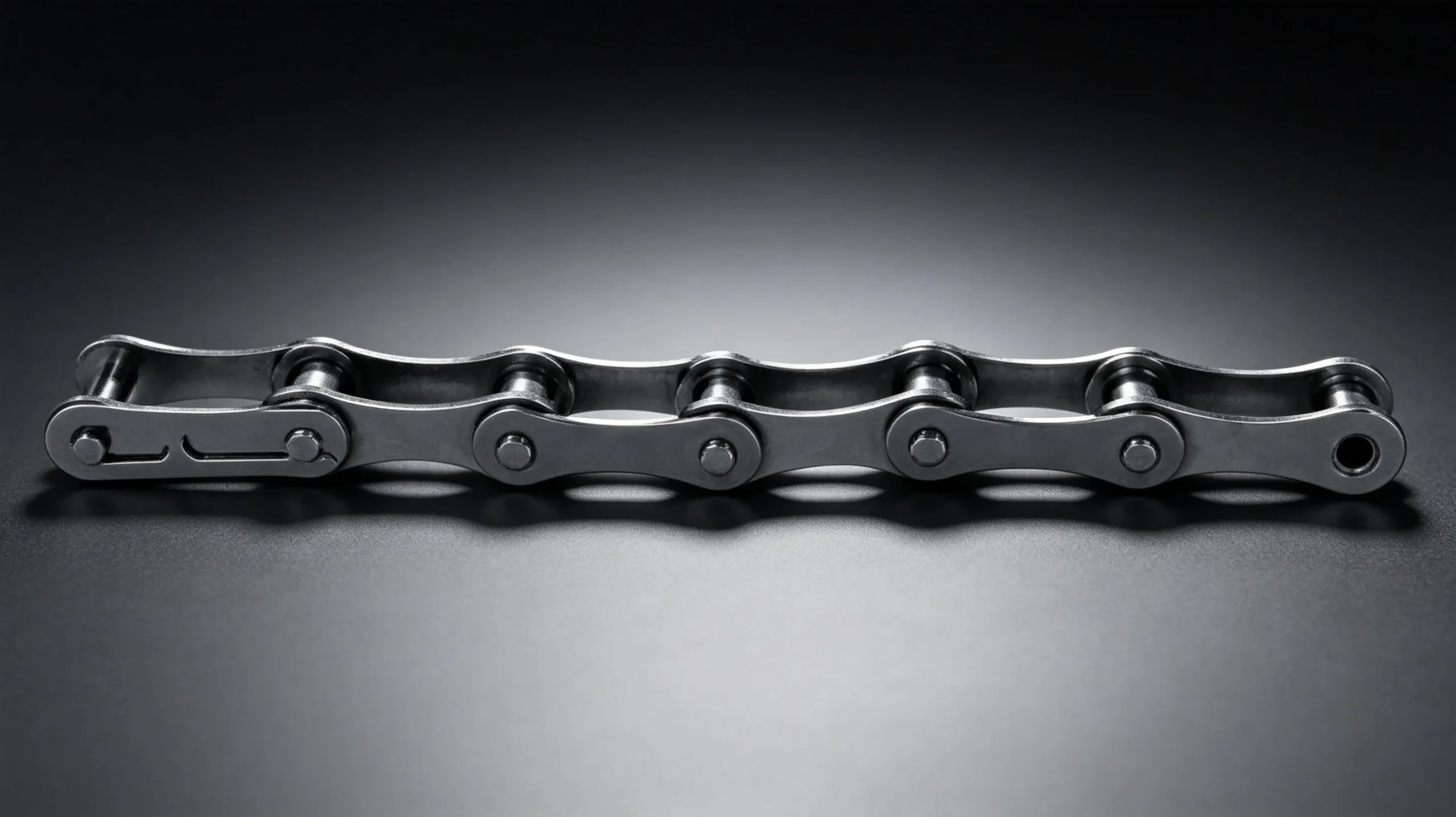
The Roller
The roller sits freely on the outside of the bushing — it is not press-fitted and is free to rotate independently of the bushing and pin. This free rotation is the defining feature of the roller chain design: when a link engages a sprocket tooth, the roller rolls up the tooth face under load rather than sliding. Rolling contact generates far less friction than sliding contact at the same load, which is why well-lubricated industrial roller chain achieves mechanical efficiency of 97 to 99 percent — among the highest of any power transmission component.
Rollers are hardened to 40 to 50 HRC — harder than the sprocket teeth they contact, which is intentional: sprocket teeth are designed to be the wear-sacrificial partner in the chain-sprocket pair. Rollers are subject to impact loading every time they engage a sprocket tooth, particularly at higher chain speeds where the impact velocity is higher. This impact can cause surface spalling (small pits) or, in extreme cases, roller cracking — a failure mode most commonly seen in drives operating beyond the rated speed for the chain pitch.
The Connecting Link
The connecting link is the removable link used to join the two ends of a chain loop and to facilitate replacement without disassembly of the driven shaft. It consists of a pair of outer plates (the connecting plate and the clip plate), two pins, and a retention element — either a spring clip, a cotter pin, or a riveted/staked end, depending on the application requirements.
Connecting links are the weakest point in a roller chain assembly, rated at 85 to 100 percent of the chain breaking load depending on the retention type. Spring clip connecting links are the most convenient for field replacement but are rated at only 85 percent of chain breaking load and are not appropriate for shock-load or vibration environments. Cottered connecting links achieve 95 percent and are appropriate for heavy industrial applications. Riveted ends achieve 100 percent but are not field-repairable.
Optional Components: Attachments and Extended Pins
Beyond the five core components, roller chain can be manufactured with various attachment features for conveyor and material handling applications. Extended pins project beyond the outer link plates to provide mounting points for conveyor attachments. Bent plates (K-type attachments) provide right-angle mounting lugs at specified link positions. Straight plates (A-type attachments) extend inward or outward from the chain centreline. These attachment features are all manufactured as integral parts of the chain link during production — they are not field-retrofittable, and chains with attachments must be specified correctly at the time of order.
EverPower Roller Chains Australia supplies complete roller chain ranges including standard, heavy series, cottered, attachment, and specialty configurations in ANSI and ISO sizes. Contact our Sydney team with your application details for a specific component and chain specification recommendation.
+61 2 9708 3322 | [email protected] | 27 Harley Crescent, Condell Park NSW 2201