
A roller chain drive that reverses direction presents design challenges that do not exist in a unidirectional drive. In a standard forward-running drive, the tight side is always the top strand and the slack side always the bottom strand. In a reversing drive, the tight and slack sides alternate with each direction change, and the chain must be tensioned correctly for both directions. Failure to account for the reversing geometry leads to chain skip during direction changes and connecting link failure from repeated load reversal.
How Tension Changes in a Reversing Drive
In a standard unidirectional roller chain drive, T₁ (tight side) = T₂ (slack side) + chain pull. In a reversing drive, when the direction reverses, the former tight side becomes the slack side and the former slack side becomes the tight side. For correct operation in both directions, the chain must be tensioned so the minimum tension (when slack) is adequate to prevent the chain from going fully slack and disengaging from the sprocket.
The key adjustment is the initial tension setting: a reversing drive must be tensioned slightly tighter than a unidirectional drive — closer to the 2 percent of centre distance sag target rather than the 3 percent upper limit — so that when the tight and slack sides reverse, the newly slack side does not become completely loose.
Connecting Link Selection for Reversing Drives
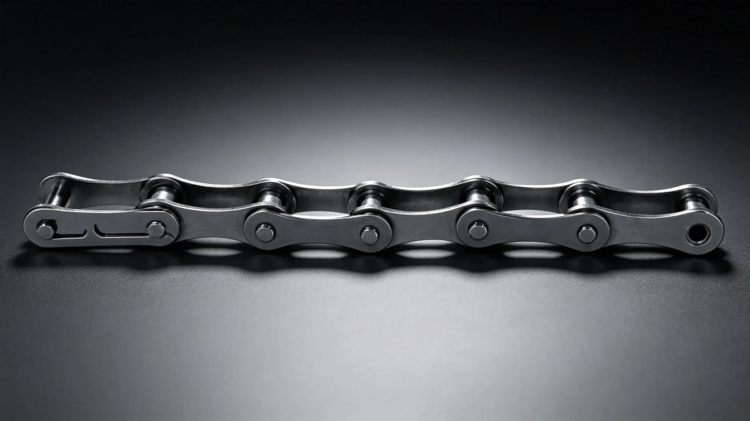
The cottered link carries 95% of chain breaking load and is rated for bidirectional loading. The spring clip link is rated for unidirectional loading and should not be used in reversing applications.
Idler Sprocket Position in Reversing Drives
For a reversing drive that uses an idler sprocket for tensioning, the idler must contact the chain on the same side in both directions — which means it must be placed midway between the two sprockets on the strand that is always the lower-tension strand in both directions (typically the shorter span). For a reversing drive where the chain path is symmetric, the optimal idler position is at the midpoint of one chain span, contacting the chain from below.
Chain Specification Adjustments for Reversing Drives
Apply an additional service factor of 1.1 to 1.3 to the design power calculation for a reversing drive, depending on the frequency and severity of direction changes. Frequent rapid reversals (multiple times per minute) require the higher factor; infrequent reversals (once per hour or less, with controlled deceleration before reversal) require only the minimum additional factor. This additional factor accounts for the dynamic peak loads that occur at the moment of direction change, when chain inertia briefly resists the direction reversal.
Minimum Chain Wrap Angle in a Reversing Drive
In a reversing drive, the effective wrap angle is the same geometrically in both directions — wrap angle is determined by drive geometry (centre distance and sprocket tooth counts), not by chain travel direction. For a symmetric two-sprocket reversing drive with equal-size sprockets (1:1 ratio), the chain wrap angle is 180 degrees on both sprockets in both directions — the ideal condition.
EverPower Roller Chains Australia supplies ANSI roller chain and cottered connecting links in all sizes for reversing drives. Contact +61 2 9708 3322 or [email protected] to discuss the correct specification for your reversing drive.
+61 2 9708 3322 | [email protected] | 27 Harley Crescent, Condell Park NSW 2201